
Datasheet


Datasheet 67
Intel
®
Celeron
®
Processor up to 1.10 GHz
NOTES:
1. These values are specified at nominal VCC
CORE
for the processor pins.
2. Thermal Design Power (TDP) represents the maximum amount of power the thermal solution is required to
dissipate. The thermal solution should be designed to dissipate the TDP power without exceeding the
maximum Tcase specification.
3. TDP does not represent the power delivery and voltage regulation requirements for the processor. Refer to
Table 5 for voltage regulation and electrical specifications.
4. T
CaseOffset
is the worst-case difference between the maximum case temperature and the thermal diode
temperature on the processor’s core. For more information refer to the document,
Intel
®
Pentium
®
III
Processor in the FC-PGA2 Package Thermal Design Guide.
5. This processor exists in both FC-PGA and FC-PGA2 packages.
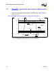
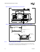
Figure 17 is a block diagram of the Intel Celeron FC-PGA/FC-PGA2 processor die layout. The
layout differentiates the processor core from the cache die area. In effect, the thermal design power
identified in Table 40 is dissipated entirely from the processor core area. Thermal solution designs
should compensate for this smaller heat flux area and not assume that the power is uniformly
distributed across the entire die area.
1. For CPUID 0x68A, the die area is 0.94 cm
2
, the cache area is 0.30 cm
2
, and the core area is 0.64 cm
2
.
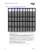
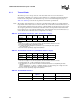
Table 41. Intel
®
Celeron
®
Processor for the FC-PGA2 Package Thermal Design Power
1
Processor
Processor Core
Frequency (MHz)
System Bus
Frequency (MHz)
Processor
Thermal Design
Power
2,3
CPUID 068Ah (W)
Maximum
T
case
4
(°C)
Additional
Notes
900 900 100 30.0 72 5
950 950 100 32.0 72 5
1 GHz 1000 100 33.9 69 5
Figure 17. Processor Functional Die Layout (CPUID 0686h)
(1)
Cache Area
0.04 in
2
0.337”
0.275”
0.146”
0.414” Core Area
0.10 in
2
Die Area
0.14 in
2
Die Area = 0.90 cm
2
Cache Area = 0.26 cm
2
Core Area = 0.64 cm
2
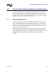
Figure 18. Processor Functional Die Layout (up to CPUID 0683h)
Cache Area
0.05 in
2
0.362”
0.292”
0.170”
0.448”
Core Area
0.11 in
2
Die Area
0.16 in
2
Die Area = 1.05 cm
2
Cache Area = 0.32 cm
2
Core Area = 0.73 cm
2