Intel® Blade Server Ethernet Switch Module IXM5414E: Installation and User’s Guide A Guide for Technically Qualified Assemblers of Intel® Identified Subassemblies/Products C66107-004
ii
Contents Safety . . . . . . . . . . . . . . . . . . . . . . . . . . . . . . . . . . . . . . . . . . . . . . . . . . . . . . . . . . . . . . . . . . . . . v 1 Introducing the Intel® Blade Server Ethernet Switch Module IXM5414E . . . . . . . 1 Related publications . . . . . . . . . . . . . . . . . . . . . . . . . . . . . . . . . . . . . . . . . . . . . . . . . . Notices and statements used in this book . . . . . . . . . . . . . . . . . . . . . . . . . . . . . . . .
Appendix A Appendix B Appendix C Appendix D Appendix E RJ-45 Pin Specifications . . . . . . . . . . . . . . . . . . . . . . . . . . . . . . . . . . 227 Cable Lengths . . . . . . . . . . . . . . . . . . . . . . . . . . . . . . . . . . . . . . . . . . . 229 Run-time Switching Software Default Settings . . . . . . . . . . . . . . . . 231 CLI Command Tree . . . . . . . . . . . . . . . . . . . . . . . . . . . . . . . . . . . . . . . 239 CLI Configuration Examples . . . . . . . . . . . . . . . . . . . . . . . .
Safety Before installing this product, read the Safety Information. Antes de instalar este produto, leia as Informações de Segurança. Pred instalací tohoto produktu si prectete prírucku bezpecnostních instrukcí. Læs sikkerhedsforskrifterne, før du installerer dette produkt. Lees voordat u dit product installeert eerst de veiligheidsvoorschriften. Ennen kuin asennat tämän tuotteen, lue turvaohjeet kohdasta Safety Information. Avant d'installer ce produit, lisez les consignes de sécurité.
Antes de instalar este producto, lea la información de seguridad. Läs säkerhetsinformationen innan du installerar den här produkten. Statement 1: DANGER Electrical current from power, telephone, and communication cables is hazardous. To avoid a shock hazard: • Do not connect or disconnect any cables or perform installation, maintenance, or reconfiguration of this product during an electrical storm. • Connect all power cords to a properly wired and grounded electrical outlet.
Statement 2: xxCAUTION: When laser products (such as CD-ROMs, DVD drives, fiber optic devices, or transmitters) are installed, note the following: • Do not remove the covers. Removing the covers of the laser product could result in exposure to hazardous laser radiation. There are no serviceable parts inside the device. • Use of controls or adjustments or performance of procedures other than those specified herein might result in hazardous radiation exposure.
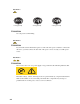
Statement 3: ≥ 18 kg (39.7 lb) ≥ 32 kg (70.5 lb) ≥ 55 kg (121.2 lb) xxCAUTION: Use safe practices when lifting. Statement 4: xxCAUTION: If you install a strain-relief bracket option over the end of the power cord that is connected to the device, you must connect the other end of the power cord to an easily accessible power source. Statement 5: xxCAUTION: Never remove the cover on a power supply or any part that has the following label attached.
Statement 6: DANGER Overloading a branch circuit is potentially a fire hazard and a shock hazard under certain conditions. To avoid these hazards, ensure that your system electrical requirements do not exceed branch circuit protection requirements. Refer to the Statement 7: xxCAUTION: Hazardous voltage, current, and energy levels might be present. Only a qualified service technician is authorized to remove the covers where the following label is attached.
x
1 Introducing the Intel® Blade Server Ethernet Switch Module IXM5414E Thank you for purchasing an Intel® Blade Server Ethernet Switch Module IXM5414E. This Installation and User’s Guide contains information about: • Setting up and installing your switch module • Configuring your switch module For installation details, see Chapter 2 “Installing and Removing the Intel® Blade Server Ethernet Switch Module IXM5414E” on page 9.
Record your product information in this table. Product name Intel® Blade Server Ethernet Switch Module IXM5414E Type _________________________________________________ Model number _________________________________________________ Serial number _________________________________________________ Media access _________________________________________________ control (MAC) address Verify that the shipping carton contains an Intel® Blade Server Ethernet Switch Module IXM5414E.
Notices and statements used in this book The caution and danger statements that appear in this book are also in the multilingual Safety Information Book on the Resource CD. Each statement is numbered to refer to the corresponding statement in the Safety Information Book. The following notices and statements are used in this book: • Note: These notices provide important tips, guidance or advice.
For more information about the components of the information panel, see Chapter 3 “Information Panel LEDs and External Ports” on page 17. For more information about the MAC address, see “IP addresses and SNMP community names” on page 21. Specifications and features The following section provides a summary of the specifications and features for your IXM5414E switch module.
• Standards The following standards apply to the IXM5414E switch module. — Switching Support – IEEE 802.3 10BASE-T Ethernet – IEEE 802.3 Auto-negotiation – IEEE 802.3u 100BASE-TX Fast Ethernet – IEEE 802.3z Gigabit Ethernet – IEEE 802.3ab 1000BASE-T – IEEE 802.1Q Tagged VLAN – IEEE 802.1p Priority – GARP – GMRP – GVRP – IEEE 802.3ac - VLAN Tagging – IEEE 802.3ad - Link Aggregation – IEEE 802.1s - Spanning Tree – IEEE 802.1w - Rapid Spanning Tree – IEEE 802.
– • Independent VLAN Learning (IVL) support • Port Mirroring • IGMP Snooping • Static MAC Filtering System Facilities • Event and Error Logging Facility • Run-time and Configuration Download Capability • PING Utility — Quality of Service (QOS) Support – – • Bandwidth Provisioning • Maximum Burst Rate (MBR) • Per Port (Interface) • Per VLAN Access Control Lists • Source IP • Destination IP • Source L4 Port • Destination L4 Port Management — RMON - Groups 1, 2, 3 and 9 supporte
— RFC 1155 - SMI v1 — RFC 1157 - SNMP — RFC 1212 - Concise MIB Definitions — RFC 1901 - Community-based SNMP v2 — RFC 1905 - Protocol Operations for SNMP v2 — RFC 1906 - Transport Mappings for SNMP v2 — RFC 1907 - Management Information Base for SNMP v2 — RFC 1908 - Coexistence between SNMP v1 and SNMP v2 — RFC 2295 - Remote Variant Selection; RSVA/1.
– • • RFC 2674 - VLAN MIB • RFC 2618 - RADIUS Authentication Client MIB • RFC 2620 - RADIUS Accounting MIB • RFC 2819 - RMON Groups 1, 2, 3 and 9 • IEEE 802.1X MIB (IEEE 802.
2 Installing and Removing the Intel® Blade Server Ethernet Switch Module IXM5414E The following illustration shows the I/O module bay locations in the SBCE platform. Attention: To maintain proper system cooling, each I/O module bay must contain either a module or a filler module; each blade bay must contain either a blade or a filler blade. Ethernet interface requirements The SBCE platform supports a minimum of one hot-swap Ethernet switch module in I/O module bay 1.
I/O module bay Switch-module function 2 Connection 2 (Ethernet Link 2) for all blade servers in the SBCE 3 Connection 3 (from all blade server interface options in the SBCE) 4 Connection 4 (from all blade server interface options in the SBCE) For additional information, see the Intel® Blade Server Chassis SBCE : Installation and User’s Guide on the Resource CD.
• Do not leave the device where others can handle and possibly damage it. • While the device is still in its static-protective package, touch it to an unpainted metal part of the SBCE platform for at least two seconds. (This drains static electricity from the package and from your body.) • Remove the device from its package and install it directly into your SBCE without setting it down. If it is necessary to set the device down, place it in its static-protective package.
SBCE Complete the following steps to install the IXM5414E switch module. 1. Review the information in “Safety” on page v and in “Installation guidelines” on page 10. 2. Remove the acoustic attenuation module, if installed, from the rear of the SBCE platform. The following illustrations show how to remove the module from the SBCE platform.
3. Select an I/O module bay in which to install the switch module, in accordance with the instructions in “Ethernet interface requirements” on page 9. 4. Remove the filler module from the selected I/O module bay. Store the filler module for future use. 5. If you have not already done so, touch the static-protective package that contains the switch module to an unpainted metal part of the SBCE platform for at least two seconds. 6. Remove the switch module from its static-protective package. 7.
Removing the IXM5414E switch module Statement 8: xxCAUTION: Never remove the cover on a power supply or any part that has the following label attached. Hazardous voltage, current, and energy levels are present inside any component that has this label attached. There are no serviceable parts inside these components. If you suspect a problem with one of these parts, contact a service technician. Complete the following steps to remove the IXM5414E switch module. 1.
4. Slide the switch module out of the I/O module bay and set it aside. 5. Place either another switch module or a filler module in the I/O module bay within 1 minute. 6. If you placed another switch module in the I/O module bay, reconnect any cables that you unplugged in Step 2. 7. Replace the acoustic attenuation module option if you removed it in step 1.
16 Intel® Blade Server Ethernet Switch Module IXM5414E
3 Information Panel LEDs and External Ports This chapter describes the information panel and LEDs (also known as indicators) on the Intel® Blade Server Ethernet Switch Module IXM5414E. This chapter also identifies the external ports on the information panel. Information panel The information panel of the IXM5414E switch module consists of LEDs and four external 1000BASE-T ports, as shown in the following illustration.
Notes: 1. The illustrations in this document may differ slightly from your hardware. 2. An amber LED illuminates when a system error or event has occurred. To identify the error or event, check the LEDs on the information panel of the switch module. OK (power-on): This green LED is located above the four external 10/100/1000 Mbps ports on the information panel. When this LED is on, it indicates that the switch module has passed the PowerOn Self-Test (POST) and is operational.
4 Switch Management and Operating Concepts This chapter discusses many of the concepts and features used to manage the Intel® Blade Server Ethernet Switch Module IXM5414E and the concepts necessary to understand how it functions. In addition, this chapter explains many important points regarding these features. Configuring the switch module to implement these concepts and use its many features is discussed in detail in the following chapters.
module by selecting this mode as an option through the management module configuration utility program (see the applicable Installation and User’s Guide publications on the Resource CD for more information). Switch module management and control This document describes the user interfaces, screens, parameters and other information that you need for remote management and control of your IXM5414E switch module. Complete the following initial configuration steps: 1.
(CLI) (see Chapter 7 “Command Line Interface Management” on page 155 for detailed information). Both interfaces provide access to the same switch information and control parameters. In addition, you can access an extensive set of both standard and private MIB objects through SNMP protocols.
The switch MAC address can also be displayed using CLI command show inventory or from the Web Interface. In addition, you can also set an IP address for a gateway router. This becomes necessary when the network management station and switch modules are located on different IP networks, requiring management packets to go through a router to reach the network manager.
nonvolatile random-access memory (NVRAM) are used to reconfigure the switch module. Warm start This trap indicates that the switch module has been restarted; however, the poweron self-test (POST) is skipped. Authentication failure This trap indicates that someone has tried to log on to the switch module using an invalid SNMP community string. The switch module automatically stores the source IP address of the unauthorized user.
You can attach a monitoring device to the mirrored port, such as a sniffer or an RMON probe, to view details about the packets that pass through the first port. This is useful for network monitoring and troubleshooting purposes. Simple Network Management Protocol (SNMP) The Simple Network Management Protocol (SNMP) is an open system interconnection (OSI) layer 7 (application layer) protocol for remotely monitoring and configuring network devices.
The aging time can be from 10 to 1,000,000 seconds, with a default value of 300 seconds. Setting the value too high could mean that some entries in the table become out of date, causing the switch module to make incorrect packet-forwarding decisions. If the aging time is too short, however, entries may be aged out too soon and have to be relearned.
For additional information about both forms of the Spanning Tree Protocol, see Appendix H on page 277. Virtual Local Area Networks (VLAN) A virtual local area network (VLAN) is a network topology configured according to a logical scheme rather than the physical layout. VLANs can be used to combine any collection of blade servers into an autonomous user group that appears as a group within one or more chassis.
headers (tag-unaware devices). The tagging feature enables VLANs to span multiple 802.1Qcompliant switches through a single physical connection and enables the Spanning Tree Protocol to be enabled on all ports and work normally. The IEEE 802.1Q standard restricts the forwarding of untagged packets to the VLAN of which the receiving port is a member. The main characteristics of IEEE 802.
IEEE 802.1Q VLAN tags The following illustration shows the 802.1Q VLAN tag. Four additional octets are inserted between the source MAC address and the packet’s EtherType field. Their presence is indicated by a value of 0x8100 in the two bytes following the MAC address, in the VLAN tag’s EtherType field, indicating that the packet carries an IEEE 802.1Q/802.1p tag.
Adding an IEEE 802.1Q Tag Dest. Src. Length/EType Data Old CRC Orginal Ethernet Packet New Tagged Packet Dest. Src. EType Priority Tag Length/EType Data New CRC VLAN ID Port VLAN ID Packets that are tagged (are carrying the 802.1Q VID information) can be transmitted from one 802.1Q compliant network device to another with the VLAN information intact. This enables 802.1Q VLANs to span network devices (and indeed, the entire network, if all network devices are 802.1Q compliant).
The forwarding function determines the destination port. If the destination, or egress, port is a member of the same VLAN as the packet the destination port transmits the packet on its attached network segment. If the egress port is not a member of the VLAN, the packet is dropped. IEEE 802.1Q VLAN configuration The switch module initially configures one VLAN (VID = 1) named DEFAULT. The factory default setting assigns all ports on the switch module to VLAN I.
GARP VLAN Registration Protocol (GVRP) GVRP (GARP VLAN Registration Protocol) is used to propagate VLAN membership information throughout the network. GVRP is based on the Generic Attribute Registration Protocol (GARP), which defines a method of propagating a defined attribute (i.e. VLAN membership) throughout the network. GVRP allows both end stations and the switch module to issue and revoke declarations relating to membership in VLANs.
The VLAN classification thus associated with received GMRP PDUs establishes the VLAN context for the received PDU, and identifies the GARP participant instance to which the PDU is directed. GMRP PDUs transmitted by GMRP participants are VLAN-classified according to the VLAN context associated with that participant. GMRP Participants in VLAN networking devices apply the same egress rules that are defined for the transmission port.
Group addresses are stored in the Multicast Forwarding Database (MFDB). An IGMP address will be removed from the database if a report for it is not received within the query interval. An interface may be removed from an IGMP group in response to an IGMP Leave Group message.Link aggregation (LAG) The Intel® Blade Server Ethernet Switch Module IXM5414E supports Link Aggregation (LAG), or port trunking.
The switch module offers link aggregation on four external ports for up to two static trunk groups or two LACP 802.3ad link aggregation groups. The trunked ports can be non-continuous (that is, have non-sequential port numbers). All of the ports in the group must be members of the same VLAN. In addition, the trunked ports must connect at the same speed in full-duplex mode.
Before loading TCP/IP with an address acquired from the DHCP server, DHCP clients check for an IP address conflict by sending an Address Resolution Protocol (ARP) request containing the address. If a conflict is found, TCP/IP does not start, and the user receives an error message. The conflicting address should be removed from the list of active leases, or it should be excluded until the conflict is identified and resolved. Security IEEE 802.
A controlled port is configured by management to be in one of three states: ForceUnauthorized The port is set to the unauthorized state. ForceAuthorized The port is set to the authorized state. Auto The port’s state will be set based on the outcome of authentication exchanges between the Supplicant, Authenticator and the Authentication server. This is the default port state when port-based access control is enabled.
Table 2. Secure Shell Feature Details SSH Feature Component Type Hash Algorithms • MD5 • SHA-1 • SHA-1-96 Key Exchange Methods Diffie-Hellman Compression Algorithms • zlib • none (i.e. no compression) • SSH-DSA • SSH-RSA • SSH 2.0 • SSH 1.5 Public Key Algorithms SSH Protocol Versions Secure Socket Layer (SSL) Managing devices with a web browser has been standard practice for several years. Unfortunately standard HTTP transactions are no more secure than Telnet.
Quality of Service (QoS) The Quality of Service (QoS) features of the Intel® Blade Server Ethernet Switch Module IXM5414E allow you to allocate network bandwidth according to the needs of the network users. This section will give you an overview of the methods available. Quality of Service technologies are intended to provide guaranteed, timely, delivery of specific application data to a particular destination.
Access Control Lists (ACL) You use Access Control Lists (ACLs) to control the traffic entering or exiting a network, for example where two networks are connected, or an internal network is connected through a firewall router to the Internet. This allows you to ensure that only authorized users have access to specific resources while blocking off any unwarranted attempts to reach them.
40 Intel® Blade Server Ethernet Switch Module IXM5414E
5 Web-Based Network Management This chapter describes how to use the Web-based network management module to access and configure the internal switching software. Important: Before you configure your Intel® Blade Server Ethernet Switch Module IXM5414E, be sure that the management modules in your SBCE platform are properly configured.
See the applicable Installation and User’s Guide on the Resource CD for additional instructions for configuring the switch module for this mode of operation. • The system administrator can select to enable remote management of the IXM5414E switch module through the four external Ethernet ports on the switch module, instead of, or in addition to, access through the management module. This mode can only be enabled through the management module configuration interface.
Click on Login, and a dialog box similar to the following will open: Enter “USERID” in the User name field and enter “PASSW0RD” (with a zero in place of the O) in the Password field. Click the OK button. This opens the main page in the management module. / NOTE The User name and Password fields are case sensitive. To increase system security, set a password after you log onto the system for the first time and be sure to store the new password in a safe location.
If java mode is enabled for the switch (the default is enabled) the top panel shows a real-time information-panel display of the switch module, as shown below. You can change the java mode on the Network Connectivity Configuration menu (See “Network connectivity” on page 49). External port status Switch module (rear view) Blade server bays Link status The panel on the left side of the screen displays the main menu.
When you first log on to the switch, you will see the System Description details in the center of the screen. For more details on the information displayed, see “System description” on page 48.
• Port • SNMP • Statistics • System utilities • Trap manager ARP cache This panel displays the connectivity between the switch and other devices. The ARP cache identifies the Media Access Control (MAC) addresses of the IP stations communicating with the switch. MAC Address IP Address Port A unicast MAC address of a device on a subnet attached to one of the switch's interfaces for which the switch has forwarding and/or filtering information.
System Description The product name of this switch. Machine Type The machine type of this switch. Machine Model The model within the machine type. Serial Number The unique box serial number for this switch. FRU Number The field-replaceable unit number. Part Number The manufacturing part number. Maintenance Level The identification of the hardware change level. Manufacturer The code that identifies the manufacturer, displayed as two two-digit hexadecimal numbers.
Operating System The operating system currently running on the switch. Network Processing Device The network processor hardware. Additional Packages The list of optional software packages installed on the switch, if any. For example, Quality of Service. Configuration The Configuration menu gives you access to panels used for switch module management.
System Description The product name of this switch. System Name The name used to identify this switch. The range for name is from 1 to 31 alphanumeric characters. System Location The physical location of this switch. May be up to 31 alphanumeric characters. The factory default is blank. System Contact The person or organization responsible for this switch. May be up to 31 alphanumeric characters. The factory default is blank. IP Address The IP address of the interface.The factory default value is 10.90.90.
IP Address The IP address of the interface.The factory default value is 10.90.90.9x, where x is determined by the number of the I/O-module bay into which you have installed the Ethernet switch module (see Table 1.“Default IP addresses based on I/O module bay numbers” on page 21). Subnet Mask The IP subnet mask for this interface. The factory default value is 255.255.255.0. Default Gateway The default IP gateway address for this interface. The factory default value is 0.0.0.0.
Click the Apply button to update the switch with new values. If you want the switch to retain the new values across a power cycle you must perform a save. Telnet Use this panel to configure Telnet settings. Telnet Login Timeout (minutes) Specify how many minutes of inactivity should occur on a Telnet or SSH session before the switch logs off. A zero means there will be no timeout. You may enter any number from 0 to 160. The factory default is 5.
User Use this pull-down menu to select one of the existing accounts, or select Create to add a new one, provided the maximum of five Read-only accounts has not been reached. User Name The name the user will use to login using the serial port, Telnet or Web. It can be up to eight alphanumeric characters and is not case-sensitive. Six user names can be defined, including the Read-only user “GUEST” which cannot be changed. The admin user will enter USERID (all caps, case sensitive) in this field.
Authentication Protocol The protocol (if any) used to authenticate the user. This field specifies the protocol to be used to authenticate a user account. The valid authentication protocols are None, MD5 or SHA. If MD5 or SHA are specified, the user login password will be used as the SNMPv3 authentication password. Encryption Protocol Specify the SNMPv3 Encryption Protocol settings for the selected user account. The valid encryption protocols are None or DES.
Login Login Name Method 1 Method 2 Method 3 Select the authentication login list you want to configure. Select Create to define a new login list. When you create a new login list, Local is set as the initial authentication method. If you are creating a new login list, enter the name you want to assign. It can be up to 15 alphanumeric characters long and is not case sensitive. The pull-down menus you use to specify authentication methods only appear after you create a list by entering a name.
ID The ID of this row. User Name The user name of user made the session. Connection From The user is connected from which machine. Idle Time The idle session time. Session Time The total session time. Click the Refresh button to update the information on the page. Login summary This panel displays a list of all users set up for each authentication login list.
Login Method List Login Users Identifies the authentication login list summarized in this row. The ordered list of methods configured for this login list. The users you assigned to this login list on the User Login Configuration screen. This list is used to authenticate the users for system login access. 802.1X Port Security Users The users you assigned to this login list on the Port Access Control User Login Configuration screen.
Each configured user is assigned to a login list that specifies how the user should be authenticated when attempting to access the switch or a port on the switch. After creating a new user account on the User Account screen, you should assign that user to a login list for the switch using this screen and, if necessary, to a login list for the ports using the Port Access Control User Login Configuration screen.
Forwarding database The first option on this menu is the Configuration panel, which allows you to configure the forwarding database aging interval. The second option is the Search panel, which displays the forwarding database entries specified by a MAC address or filter you enter. Configuration Use this panel to configure the forwarding database aging interval.
Filter Specify the entries you want displayed from the pull-down menu. Once a choice is made the list is automatically refreshed with the selected filter. Filter choices are: Learned Only MAC addresses that have been learned will be displayed. All The entire table will be displayed. MAC Address Search You may also search for an individual MAC address.
Management The value of the corresponding instance is also the value of an existing instance of dot1d StaticAddress. Currently this is used when enabling VLANs for routing. Self The MAC address of one of the switch’s physical interfaces. GMRP Learned The value of the corresponding instance was learned via GARP Multicast Registration Protocol (GMRP). Other The value of the corresponding instance does not fall into one of the other categories. Click the Search button to search for the specified MAC address.
Time File Line Description The time the event occurred, calculated from the time the switch was last reset, in days, hours, minutes and seconds. The source code filename identifying the code that detected the event. The line number within the source file of the code that detected the event. An explanation of the problem being reported. Click the Refresh button to retrieve and display the database again starting with the first entry in the table.
Entry Filename Line TaskID Code Time The number of the entry within the event log. The most recent entry is first. The source code filename identifying the code that detected the event. The line number within the source file of the code that detected the event. The OS-assigned ID of the task reporting the event. The event code passed to the event log handler by the code reporting the event. The time the event occurred, measured from the previous reset, in days, hours, minutes and seconds.
Port Port Type Selects the interface for which data is to be displayed or configured. For normal and LAG ports this field will be blank. Otherwise the possible values are: Probe Monitoring port, participating in Port Mirroring. Following is how this panel displays when the port type is Probe.
Mirrored Port being mirrored. LAG Member of a Link Aggregation (LAG) trunk. Following is how this panel displays when the port type is LAG. STP Mode Select the Spanning Tree Protocol (STP) Administrative Mode for the port or LAG. The possible values are Enabled and Disabled. Admin Mode Use the pull-down menu to select the port control administration state. You must select Enabled if you want the port to participate in the network. The factory default is Enabled.
Link Status Indicates whether the Link is Up or Down. Following is how this panel displays when the link status is link up. Link Trap This object determines whether or not to send a trap when link status changes. The factory default is Enabled. The ifIndex of the interface table entry associated with this port. ifIndex Click the Apply button to update the switch with the values you entered. If you want the switch to retain the new values across a power cycle you must perform a save.
Port Port Type Identifies the physical port. If not blank, this field indicates that this port is a special type of port. The possible values are: Mirrored Port being mirrored. Probe Probe port, participating in Port Mirroring. LAG Member of a link aggregation trunk. STP Mode The Administrative Mode for the port or LAG. The possible values are Enabled and Disabled. Forwarding State The port’s current spanning tree state. This state controls what action a port takes on receipt of a frame.
Control Mode Displays whether flow control is Enabled or Disabled on this port. The following displays the right side of the panel. Descriptions of these fields follow. LACP Mode Displays whether Link Aggregation Control Protocol (LACP) is Enabled or Disabled on this port. Physical Mode Displays the selected port speed and duplex mode. If auto-negotiation support is selected, then the duplex mode and speed will be set by the auto-negotiation process.
Port Mirroring Mode Select the Port Mirroring Mode by selecting the corresponding line on the pulldown entry field. The factory default is Disabled. Probe Port The interface you want to act as the Probe. Once configured there is no network connectivity on the probe port. The probe port will not forward or receive any traffic. The probe tool attached to the probe port will not be able to ping the switch or through the switch, and nobody will be able to ping the probe tool.
Community configuration By default, two SNMP Communities exist: • private, with Read/Write privileges and status set to Enable • public, with Read-only privileges and status set to Enable These are well-known communities; you can use this menu to change the defaults or to add other communities. Only the communities that you define using this menu will have access to the switch using the SNMPv1 and SNMPv2c protocols.
same community name, the first entry is kept and processed and all duplicate entries are ignored. Client IP Address Enter the IP address (or portion thereof) from which this device will accept SNMP packets with the associated community name. The requesting entity's IP address is ANDed with the Client IP mask before being compared to the Client IP address. Note that if the Client IP mask is set to 0.0.0.0, an IP address of 0.0.0.0 matches all IP addresses. The default value is 0.0.0.0.
Community Name IP Address Status This field adds an SNMP trap receiver community name and associated IP address. Enter the community string for the SNMP trap packet to be sent to the trap manager. This may be up to 16 characters and is case sensitive. Enter the IP address to receive SNMP traps from this device. This field Enables or Disables the SNMP trap receiver identified by trap receiver community name and IP address. Enabled trap receivers are active (able to receive traps).
Community IP Address Status Displays the community string for the SNMP trap packet to be sent to the trap manager. Note that trap receiver communities and SNMP communities are separate and distinct. Displays the IP address to receive SNMP traps from this device. Indicates whether traps are currently Enabled for this community: Enable Traps will be sent. Disable Traps will not be sent. Supported Management Information Bases (MIB) This panel displays a list of all the MIBs supported by the switch.
Name Description The RFC number if applicable and the name of the MIB. The RFC title or MIB description. Click the Refresh button to retrieve and display the database again starting with the first entry in the table. Statistics This menu provides access to menu options that display various switch statistics, including: • Switch detailed • Switch summary • Port detailed • Port summary Switch detailed This panel displays detailed statistics for all CPU traffic.
ifIndex This object indicates the ifIndex of the interface table entry associated with the processor of this switch. Received Octets Received The total number of octets of data received by the processor (excluding framing bits but including FCS octets). Packets Received Without Error The total number of packets (including broadcast packets and multicast packets) received by the processor. Unicast Packets Received The number of subnetwork-unicast packets delivered to a higher-layer protocol.
Octets Transmitted The total number of octets of data transmitted on the network including framing bits. Packets Transmitted Without Errors The total number of packets that have been transmitted on the network without an error occurring. Unicast Packets Transmitted The total number of packets that higher-level protocols requested be transmitted to a subnetwork-unicast address, including those that were discarded or not sent.
Click the Clear Counters button to clear all the counters, resetting all summary and switch detailed statistics to defaults, except for the counts of discarded packets, which cannot be cleared. Click the Refresh button to refresh the data on the screen with the present state of the data in the switch. Switch summary This panel displays a summary of the statistics for CPU traffic. ifIndex This object indicates the ifIndex of the interface table entry associated with the processor of this switch.
Transmit Packet Errors The number of outbound packets that could not be transmitted because of errors. Address Entries Currently In Use The number of learned and static Forwarding Database Address Table entries currently in use by this switch module. VLAN Entries Currently In Use The number of VLANs currently in the VLAN table on this switch module. Time Since Counters Last Cleared The elapsed time in days, hours, minutes and seconds since the statistics for this port were last cleared.
Octets Received The total number of octets of data (including those in bad packets) received on the network (excluding framing bits but including FCS octets). This object can be used as a reasonable estimate of Ethernet utilization. If greater precision is desired, the etherStatsPkts and etherStatsOctets objects should be sampled before and after a common interval.
Jabbers Received The total number of packets received that were longer than 1518 octets (excluding framing bits, but including FCS octets), and had either a bad Frame Check Sequence (FCS) with an integral number of octets (FCS Error) or a bad FCS with a non-integral number of octets (Alignment Error). Note that this definition of jabber is different than the definition in IEEE802.3 section 8.2.1.5 (10BASE5) and section 10.3.1.4 (10BASE2).
Packets Transmitted 1024-1518 Octets The total number of packets (including bad packets) transmitted that were between 1024 and 1518 octets in length (excluding framing bits but including FCS octets). Packets Transmitted 1519-1522 Octets The total number of packets (including bad packets) transmitted that were between 1519 and 1530 octets in length (excluding framing bits but including FCS octets). Max Info The maximum size of the information (non-MAC) field that this port will receive or transmit.
Excessive Collision Frames The number of packets which were not successfully transmitted because of excessive collisions. STP BPDUs Received The number of STP BPDUs (Bridge Protocol Data Units) received by the spanning tree layer. STP BPDUs Transmitted The number of STP BPDUs transmitted from the spanning tree layer. RSTP BPDUs Received The number of RSTP BPDUs received at the selected port. RSTP BPDUs Transmitted The number of RSTP BPDUs transmitted from the selected port. 802.
Click the Clear Counters button to clear all the counters, resetting all statistics for this port to default values. Click the Clear All Counters button to clear all the counters for all ports, resetting all statistics for all ports to default values. Click the Refresh button to refresh the data on the screen with the present state of the data in the switch. Port summary This panel displays a summary of the statistics for a specified port.
Port Use this field to select the port for which to display statistics. Click the down arrow to display the list of ports from which to choose. ifIndex This object indicates the ifIndex of the interface table entry associated with this port on an adapter. Total Packets Received Without Errors The total number of packets (including multicast and broadcast packets) received on this port without an error occurring.
Click the Clear All Counters button to clear all the counters for all ports, resetting all statistics for all ports to default values. Click the Refresh button to refresh the data on the screen with the present state of the data in the switch. System utilities This menu provides access to several systems-related panels.
Reset configuration to defaults Click the Reset button to reset the configuration of the switch module to the factory defaults. The switch is automatically reset when this command is processed. All configuration changes that you have made, including those saved to NVRAM, will be lost. You are prompted to confirm that the reset should proceed. Reset passwords to defaults Click the Reset button to reset all user passwords to the factory defaults (since only the ADMIN can set passwords, this is blank).
Download file to switch Use this panel to configure the information needed to download a file to the switch.
File Type Specify the type of file to be downloaded to the switch: Code 8051 MCU Code Config SSH RSA1 Key File SSH RSA2 Key PEM File SSH DSA Key PEM File SSL Trusted Root Certificate PEM File SSL Server Certificate PEM File SSL DH Weak Encryption Parameter PEM File SSL DH Strong Encryption Parameter PEM File 8051 MCU Code TFTP Server IP Address Enter the IP address of the TFTP server. The factory default is 0.0.0.0.
Upload file from switch Use this panel to configure the information needed to upload a file from the switch. See the previous menu option “Download file to switch” on page 86 for more information about specifying TFTP File Paths and Names. File Type This field sets the type of file to be uploaded from the switch. The datatype is one of the following: config Configuration file errorlog Error log msglog Message log TFTP Server IP Address Enter the IP address of the TFTP server. The factory default is 0.0.0.
Ping Use this panel to have the switch transmit a Ping request to a specified IP address. This checks whether the switch can communicate with a particular IP device. Once you click the Apply button, the switch will send three pings and the results will be displayed in the Ping field, below the IP address. The switch can be pinged from any IP workstation with which the switch is connected through the default VLAN (VLAN 1), as long as there is a physical path between the switch and the workstation.
Authentication Indicates whether authentication failure traps will be sent (Enable) or not (Disable). This field Enables or Disables the Authentication Flag, which determines whether a trap message is sent when the switch detects an authentication failure. The factory default is Enabled. Link Up/Down Indicates whether a trap will be sent when the link status changes from Up to Down or vice versa. This field Enables or Disables Link Up/Down traps for the entire switch.
Number of Traps Since Last Reset The number of traps that have occurred since the last time the switch was reset. Number of Traps Since Log Last Viewed The number of traps that have occurred since the traps were last displayed. Displaying the traps by any method (terminal interface display, Web display, upload file from switch, etc.) will cause this counter to be cleared to 0. Log The sequence number of this trap.
• Spanning tree VLAN This menu provides access to Virtual Local Area Network (VLAN) configuration, displays status and displays summary information. Menu options are: • Configuration • Status • Port configuration • Port summary • Reset configuration Configuration This panel displays detailed information, including interface information, for a specific VLAN. You also use it to create new VLANs.
VLAN Type always has a name of Default. Use this field to change an existing Name. This field is optional. What type of VLAN this is. A VLAN can be: • the Default VLAN (VLAN ID = 1). • a Static VLAN, one that you create using this panel or the config vlan create command. • a Dynamic VLAN, one that is created by GVRP registration. In order to change a VLAN from Dynamic to Static, use this panel or the config vlan makestatic command.
Exclude Tagging This port is never a member of this VLAN. This is equivalent to registration forbidden in the IEEE 802.1Q standard. Autodetect This port will not participate in this VLAN unless a GVRP join request is received on this port. This is equivalent to registration normal in the IEEE 802.1Q standard. Use the pull-down menu to configure the tagging behavior of this port in this VLAN. The default is untagged. Tagged All frames transmitted for this VLAN will be tagged.
In order to change a VLAN from Dynamic to Static, use the VLAN Configuration panel or the config vlan makestatic command. Broadcast Storm Control Mode This field shows the mode of broadcast storm control on the VLAN. If storm control is Enabled, storms are controlled by counting the number of broadcast packets within a certain time period. If a count limit is exceeded, the packets are discarded. Broadcast Packets/Second The rate level at which the broadcast packets will begin being discarded.
it receives. If you select Admit All, untagged and priority tagged frames received on the port will be accepted and assigned the value of the Port VLAN ID for this port. Whichever you select, VLAN tagged frames will be forwarded in accordance with the IEEE 802.1Q VLAN standard. The factory default is Admit All. Port Priority Specify the default 802.1p priority for the port. Click the Apply button to update the switch with the values on this screen.
Reset configuration All VLAN configuration parameters are reset to their factory default values if you click the Reset button and confirm your selection on the next screen. Also, all VLANs, except for the default VLAN, will be deleted. The factory default values are: • All ports are assigned to the default VLAN of 1. • All ports are configured with a PVID of 1. • All ports are configured to an Acceptable Frame Types value of Admit All Frames.
To add a new filter, select Create Filter from the top of the list. Up to 48 static MAC filters may be created. MAC Address The MAC address of the filter in the format 00-01-1A-B2-53-4D. You can only change this field when you have selected the Create Filter option.
MAC Address The MAC address of the filter in the format 00-01-1A-B2-53-4D. VLAN ID The VLAN ID associated with the filter. Destination Port Members A list of the ports to which packets with the MAC address and VLAN ID may be forwarded. GARP This menu provides access to the Generic Attribute Registration Protocol (GARP) summary and configuration panels.
Port GVRP Mode Indicates whether the GVRP administrative mode for the port is Enabled or Disabled. The factory default is Disabled. Port GMRP Mode Indicates whether the GMRP administrative mode for the port is Enabled or Disabled. The factory default is Disabled. Join Timer (centisecs) Specifies the time between the transmission of GARP PDUs registering (or re-registering) membership for a VLAN or multicast group in centiseconds. An instance of this timer exists for each GARP participant for each port.
GVRP Mode Choose the GVRP administrative mode for the switch by selecting Enable or Disable from the pull-down menu. The factory default is Disable. GMRP Mode Choose the GMRP administrative mode for the switch by selecting Enable or Disable from the pull-down menu. The factory default is Disable. Click the Apply button to update the switch with the values you enter. If you want the switch to retain the new values across a power cycle you must perform a save.
Port Select the port you want to configure from the pull-down list, or select all ports. Port GVRP Mode Specify the GVRP administrative mode for the port by selecting Enable or Disable from the pull-down menu. If you select Disable, the protocol will not be active and the Join Time, Leave Time and Leave All Time will have no effect. The factory default is Disable. Port GMRP Mode Specify the GMRP administrative mode for the port by selecting Enable or Disable from the pull-down menu.
centiseconds (10 seconds). An instance of this timer exists for each GARP participant for each port. Click the Apply button to update the switch with the values you enter. If you want the switch to retain the new values across a power cycle you must perform a save. IGMP snooping This menu provides access to the Internet Group Management Protocol (IGMP) snooping configuration and status screens.
than the Group Membership Interval. Multicast Router Present Expiration Time (secs) Specify the amount of time you want the switch to wait to receive a query on an interface before removing it from the list of interfaces with multicast routers attached. Enter a value between 0 and 3600 seconds. The default is 0 seconds. A value of zero indicates an infinite timeout, i.e. no expiration. Multicast Control Frame Count The number of multicast control frames that are processed by the CPU.
LAG This menu provides access to the Link Aggregation (LAG) configuration and status screens. Menu options are: • Configuration • Status Configuration Use this panel to configure a new LAG, assign a name to it and generate a logical port number for it. The logical port number will be displayed after the LAG has been created. LAG Name (Create) Use this pull-down menu to select one of the existing LAGs, or select Create to add a new one. There can be a maximum of 9 LAGs.
STP Mode Sets the STP mode for the specified LAG(s). Port Identifies a physical port. To add the port to the LAG select Include from the Participation column. There can be a maximum of 8 member ports in a LAG. Participation For each port specify whether it is to be included as a member of this LAG or not. The default is exclude. There can be a maximum of 8 ports assigned to a LAG. Membership Conflicts Shows ports that are already members of other LAGs. A port may only be a member of one LAG at a time.
STP Mode Link Trap The Spanning Tree Protocol Administrative Mode associated with the LAG. The possible values are: Disable Spanning tree is Disabled for this LAG. Enable Spanning tree is Enabled for this LAG. Indicates whether or not a trap will be sent when link status changes. The factory default is Enabled. Member Ports A listing of the ports that are members of this LAG, in port notation. There can be a maximum of 8 ports assigned to a given LAG.
MAC Address Enter a MAC address and VLAN pair for which the switch has forwarding and/or filtering information. The format is two two-digit hexadecimal numbers representing the VLAN and six two-digit hexadecimal numbers representing the MAC address, separated by hyphens; for example, 00-01-00-23-45-67-89-AB. After you have entered a MAC address click the Search button and the data associated with the address will be displayed. Otherwise, all entries will be displayed.
Type Description Ports representing the VLAN and six two-digit hexadecimal numbers representing the MAC address, separated by hyphens; for example, 00-01-00-23-45-67-89-AB. Displays the type of the entry. Static entries are those that are configured by the end user. Dynamic entries are added to the table as a result of a learning process or protocol. The text description of this multicast table entry. Possible values are Management Configured, Network Configured and Network Assisted.
Click the Refresh button to update the screen with the latest information. Stats This panel displays the MFDB statistics. Max MFDB Table Entries Displays the total number of entries possible in the MFDB table. Most MFDB Entries Since Last Reset Displays the largest number of entries that have been present in the MFDB table since last reset. This value is also known as the MFDB high-water mark. Current Entries Displays the current number of entries in the MFDB table.
Spanning Tree Admin Mode Select Enable or Disable from the pull-down menu to specify whether spanning tree operation is Enabled on the switch. Force Protocol Version Specify the version of the Spanning Tree Protocol (STP) you want the switch to use. The options are IEEE 802.1D (standard) and IEEE 802.1w (Rapid Reconfiguration). Configuration Digest Key A derived value identifying the configuration. Click the Refresh button to update the screen with the most recent data.
Bridge Priority Specifies the bridge priority. The value may be between 0 and 61440. It is set in multiples of 4096. For example, if you enter any value between 0 and 4095, it will be set to 0. If you enter any value between 4096 and (2*4096-1) it will be set to 4096. The default priority is 32768. Bridge Max Age (secs) Specifies the bridge maximum age timeout value.
Topology Change The value of the topology change parameter for the switch indicating if a topology change is in progress on any port on the bridge. It takes a value if True or False. Designated Root The bridge identifier of the root bridge. Root Path Cost Path Cost to the Designated Root for this bridge instance. Root Port Port to access the Designated Root. Max Age (secs) Path Cost to the Designated Root for this bridge instance.
Port Priority Specify the priority for the selected port. The port priority is set in multiples of 16, and the range is 0 to 240. Admin Edge Port Select Enable to specify the port as an Edge Port within the CST. Disable is the default. Port Path Cost Set the Path Cost to a new value for the specified port. The range is 1 to 200000000. Auto-calculate Port Path Cost Displays whether the path cost is automatically calculated (Enabled) or not (Disabled).
CST Path Cost Path Cost to the CST Regional Root. Click the Apply button to send the updated screen to the switch and cause the changes to take effect on the switch. If you want the switch to retain the new values across a power cycle you must perform a save. Click the Force button to force the port to send out 802.1w BPDUs. Click the Refresh button to update the screen with the most recent data. Statistics This panel displays BPDU statistics for the selected port.
802.1p priority mapping Use this panel to specify how IEEE 802.1p priority classes are to be mapped to the switch’s internal traffic classes. User Priority The 802.1p user priority to be mapped. Traffic Class Use the pull-down menus to select the internal traffic class for each user priority. Click the Apply button to send the updated screen to the switch and cause the changes to take effect on the switch. If you want the switch to retain the new values across a power cycle you must perform a save.
• Port configuration • Port status • Port summary • Statistics • Login • Port access privileges • Port access summary Configuration Use this panel to enable or disable authentication support on the switch. In disabled mode, the IEEE 802.1X configuration is retained and can be changed, but it is not activated. Administrative Mode Lists the two options for administrative mode: Enable and Disable. The default value is Disable.
Port Select the port to be configured. When the selection is changed, a screen refresh will occur causing all fields to be updated for the newly selected port. All physical interfaces are valid. Control Mode Lists the options for control mode. The control mode is only set if the port is in Link Up status. The options are: Force Unauthorized The authenticator Port Access Entity (PAE) unconditionally sets the controlled port to unauthorized.
Transmit Period (secs) Configures the transmit period for the selected port. The transmit period is the value, in seconds, of the timer used by the authenticator state machine on the specified port to determine when to send an Extensible Authentication Protocol Over LAN (EAPOL) EAP Request/Identity frame to the supplicant. The transmit period range is 1 to 65535. The default value is 30. Supplicant Timeout (secs) Specify the supplicant timeout for the selected port.
Port Select the port whose information will be displayed. When the selection is changed, a screen refresh will occur causing all fields to be updated for the newly selected port. All physical interfaces are valid. Control Mode Displays the configured control mode for the specified port. Options are: force unauthorized The authenticator port access entity (PAE) unconditionally sets the controlled port to unauthorized.
the supplicant. The transmit period range is 1 to 65535. Supplicant Timeout (secs) Displays the configured supplicant timeout for the selected port. The supplicant timeout is the value, in seconds, of the timer used by the authenticator state machine on this port to timeout the supplicant. The supplicant timeout range is 1 to 65535. Server Timeout (secs) Displays the configured server timeout for the selected port.
• Aborting • Held • Force Authorized • Force Unauthorized Backend State Displays the current state of the backend authentication state machine. Possible values are: • Request • Response • Success • Fail • Timeout • Initialize • Idle Click the Refresh button to update the information on the page. Port summary This panel displays a summary of the IEEE 802.1X configuration parameters for all switch ports. Port The port whose settings are displayed in the associated table row.
Force Unauthorized The authenticator port access entity (PAE) unconditionally sets the controlled port to unauthorized. Force Authorized The authenticator PAE unconditionally sets the controlled port(s) to authorized mode. Auto The authenticator PAE sets the controlled port(s) mode to reflect the result of the authentication exchanges between the supplicant, authenticator and authentication server. Operating Control Mode Displays the control mode under which the port is actually operating.
Port Select the port whose information is to be displayed. When the selection is changed, a screen refresh occurs causing all fields to be updated for the newly selected port. All physical interfaces are valid. EAPOL Frames Received The number of valid EAPOL frames of any type that have been received by this authenticator. EAPOL Frames Transmitted The number of EAPOL frames of any type that have been transmitted by this authenticator.
EAP Request/ID Frames Transmitted The number of EAP request/identity frames that have been transmitted by this authenticator. EAP Request Frames Transmitted The number of EAP request frames (other than request/identity frames) that have been transmitted by this authenticator. Invalid EAPOL Frames Received The number of EAPOL frames that have been received by this authenticator with an invalid length.
Click the Refresh button to update the information on the page. Click the Apply button to send the updated screen to the switch and cause the changes to take effect on the switch. Port access privileges Use this panel to add the specified user to the list of users with access to the specified port(s). By default, a user is given access to all ports. Port Users Select a port from the pull-down menu. All physical ports are available for this selection.
Port Users The port whose information is displayed on this line. The locally configured users with access to the specified port. Click the Refresh button to update the information on the page.
attempt, all user interfaces are blocked until the RADIUS application returns a response. Current Server IP Address The IP address of the current server. This field is blank if no servers are configured. Number of Configured Servers The number of RADIUS servers that have been configured. The range for this value is 0 to 3. Max Number of Retransmits The value of the maximum number of times a request packet is retransmitted. The valid range is 1 - 15.
RADIUS Server IP Address Select the RADIUS Server to be configured. Select Add to add a new server. Port The User Datagram Protocol (UDP) port used by this server. The valid range is 0 - 65535. Secret The shared secret for this server. The data entered in this field will not be displayed. Apply The Secret is applied only if this box is checked. If the box is not checked, anything entered in the Secret field has no affect and is not retained. This field is only displayed if the user has Read/Write access.
RADIUS statistics This panel displays RADIUS statistics for the switch that are not associated with a specific server or accounting server. Invalid Server Addresses The number of RADIUS Access-Response packets received from unknown addresses. Click the Refresh button to update the information on the page. Server statistics This panel displays the statistics for a configured RADIUS server.
RADIUS Server IP Address Select the IP address of the server whose information is to be displayed. Round Trip Time (secs) The time, in seconds, between the most recent RADIUS Access-Reply/AccessChallenge and the matching Access-Request from this RADIUS server. Access Requests The number of RADIUS Access-Request packets sent to this server, not including retransmissions. Access Retransmissions The number of RADIUS Access-Request packets retransmitted to this server.
Pending Requests The number of RADIUS Access-Request packets sent to this server that have not yet timed out or received a response. Timeouts The number of RADIUS packets sent to this server that have timed out. Unknown Types The number of RADIUS packets of unknown type received from this server. Packets Dropped The number of RADIUS packets received from this server dropped for a reason not otherwise included in this list. Click the Refresh button to update the information on the page.
Secret Configured Indicates whether the shared secret for this accounting server has been configured. Click the Apply button to send the updated screen to the switch and cause the changes to take effect on the switch. If you want the switch to retain the new values across a power cycle you must perform a save. Click the Remove button to remove the selected accounting server from the configuration. This button is only available to Read/Write users.
Malformed Accounting Responses Displays the number of malformed RADIUS Accounting-Response packets received from this server. Malformed packets include packets with an invalid length. Bad authenticators and unknown types are not included as malformed accounting responses. Bad Authenticators Displays the number of RADIUS Accounting-Response packets that contained invalid authenticators received from this accounting server.
HTTPS Admin Mode Select Enable or Disable to turn the Administrative Mode of Secure HTTP on or off. The currently configured value is shown when the web page is displayed. The default value is Disable. TLS Version 1 Select Enable or Disable to turn Transport Layer Security (TLS) Version 1.0 on or off. The currently configured value is shown when the web page is displayed. This field cannot be changed while HTTPS Admin Mode is enabled. The default value is Enable.
Secure Shell Secure Shell (SSH) is the standard encryption protocol used to provide a secure interactive login over a network. This Secure Shell menu provides access to the SSH configuration panel. Configuration Use this panel to configure SSH variables. Admin Mode Select Enable or Disable to turn the Administrative Mode of SSH on or off. The currently configured value is shown when the web page is displayed. The default value is Disable.
Click the Submit button to send the updated screen to the switch and have the changes take effect on the switch If you want the switch to retain the new values across a power cycle you must perform a save. Click the Refresh button to display the current page with the latest settings and status.
ACL Make a selection from the pull-down menu. You may create a new ACL or update the configuration of an existing ACL. ACL ID ACL ID must be a whole number between 1 and 100. Ports This dynamic multi-selector lists all available valid interfaces for ACL mapping. All nonrouting physical interfaces and interfaces participating in LAGs that are not already assigned to an ACL are listed. You can map an interface to one and only one ACL, but multiple interfaces can be assigned to one ACL.
Summary This panel displays a summary of all ACLs on the switch. ACL Rules Ports Direction The ACL identifier. The number of rules that are associated with this ACL. The interfaces that are associated with this ACL. The packet filtering direction for the ACL on the interface. Click the Refresh button to update the screen with the latest information. Rule configuration This panel configures the rules associated with an ACL When the screen first displays you will see the first four fields described below.
ACL Use the pull-down menu to select the ACL for which you want to create or update a rule. Rule Enter a whole number in the range of 1 to 10 that will be used to identify the rule. An ACL may have up to 10 user-specified rules. Action Specify what action should be taken if a packet matches the rule’s criteria. Permit means that matching traffic will be accepted, Deny means that it will be excluded. Match Every Select True or False from the pull-down menu.
Protocol Keyword Specify that a packet’s IP protocol is a match condition for the selected ACL rule. If you click Configure on this line you will be shown a new screen where you can select the protocol to be used as the match condition. The possible values are ICMP, IGMP, IP, TCP, and UDP. Either the Protocol Keyword field or the Protocol Number field can be used to specify an IP protocol value as a match criterion.
Source L4 Port Keyword Specify that a packet’s source Layer 4 port is a match condition for the selected ACL rule. If you click Configure on this line you will be shown a new screen where you can select the port to be used as the match condition. The possible values are domain, echo, FTP, ftpdata, HTTP, SMTP, SNMP, Telnet, TFTP, and www. Each of these values translates into its equivalent port number, which is used as both the start and end of the port range.
Bandwidth Profile Select Create from the pull-down menu to configure a new bandwidth profile, or select one of the existing profiles to display and update its configuration. Bandwidth profile 1, named default, always exists and you cannot change or delete it. Name Enter the name you want to give to the bandwidth profile. You may enter up to 15 alphanumeric characters and may include the underscore _ or the dash -. You cannot change the name after the initial configuration.
Bandwidth Profile Displays the number associated with the bandwidth profile. Name Displays the name of the bandwidth profile. Allocated Minimum Bandwidth Displays the sum of the minimum guaranteed bandwidth for all bandwidth profiles configured on this interface. Maximum Bandwidth Displays the sum of the maximum allowable bandwidth for all bandwidth profiles configured on this interface. Traffic class configuration Use this panel to create a traffic class.
Traffic Class Select Create from the pull-down menu to configure a new Traffic Class, or select one of the existing classes to display and update its configuration. Name Enter the name to be given to the Traffic Class. You may enter up to 15 alpha-numeric characters and may include the underscore _ or the dash -. You cannot change the name after the initial configuration. Weight Enter the weight to be assigned to the Traffic Class. The weight must be a decimal number from 1 to 1024.
There is no restriction on the sum of the maximum bandwidth of all Traffic Classes associated with the same interface. When a Traffic Class is attached to a LAG interface, the bandwidth allocation profile minimum bandwidth parameter will not be applicable to the Traffic Class. Click the Apply button to send the updated screen to the switch and cause the changes to take effect on the switch. If you want the switch to retain the new values across a power cycle you must perform a save.
Interface allocation summary This panel displays the bandwidth allocated to the listed interfaces. The allocated minimum bandwidth does not exceed the capability of the interface unless the interface is a LAG. Interface The Port designation of an interface for which you have configured one or more traffic classes. Nominal Bandwidth (Mbps) The interface's nominal bandwidth in Mbps. This number is only known for physical interfaces.
148 Intel® Blade Server Ethernet Switch Module IXM5414E
6 Updating the Ethernet Switch Software Two types of software run on the Ethernet switch module: the software image and the MicroController Unit (MCU) code. You can update both the software image and the code, using either the switch module's CLI commands through a Telnet session, or by using the switch module's web interface.
Obtaining the latest version To determine the latest version of the switch module software, available from Intel, complete the following steps: 1. Go to http://downloadfinder.intel.com. 2. Enter "IXM5414E" in the download search box and click "Go". A Results window opens, displaying a list of links to the current software update. 3. Compare the software version that you had noted from the I/O Module Firmware VPD section with the version of the latest software update.
8. Review the information on the screen and enter 'y' when prompted to confirm the correctness of the entries. After confirmation, the MCU code is transferred to the switch from the TFTP server. After successful update, the switch module is automatically powered off. 9.
Upgrading the MCU code using web interface To upgrade the switch MCU code using the Web interface, complete the following steps: 1. Log on to the management module web interface. 2. From the I/O Module Tasks menu, click Management / Advanced Management. 3. Click Start Web Session; then, logon to the Ethernet switch module. 4. From the System Utilities menu, click Download File to Switch. The "Download File to Switch" window opens. 5. Enter the following information in the "Download file to Switch" window.
4. 5. 6. 7. Click Power Off Module(s). Select the I/O-module bay on which the software update is installed, again. Click Power On Module(s). Wait 70 seconds for POST to be completed Make sure that the latest switch operating-system software is correctly installed on the Ethernet switch module. From the Monitors menu, click Firmware VPD. The Firmware VPD window opens. 8. In the Firmware VPD window, locate the I/O Module Firmware VPD section.
154 Intel® Blade Server Ethernet Switch Module IXM5414E
7 Command Line Interface Management Your Intel® Blade Server Ethernet Switch Module IXM5414E supports a management interface that you can use to set up and control your device over the network using the TCP/IP Telnet protocol. You can use this facility to perform the same network management functions that you can perform using the Web Interface. You can also use the Telnet interface to configure the switch module for management using an SNMP-based network management system.
• Entering Ctrl-Z will return you to the root level command prompt. Parameters The following conventions apply to the parameters: • Parameters are order dependent. • Parameters are displayed in this document in bold italic font, which must be replaced with a name or number. • To use spaces as part of a name parameter, enclose it in double quotes, for example, “System Name with Space”. • Parameters may be required or optional, and may have a list of choices.
character strings Use double quotation marks to identify character strings, for example, “System Name with Spaces”. An empty string (“”) is not valid. Comments When you are writing a test or configuration script you may add comments by using the “#” character to flag the beginning of a comment. The comment flag character can begin a word anywhere on the command line, and all input following this character will be ignored.
!n !str !*str ? execute the nth command in history buffer execute the most recent command that starts with the string “str”. execute the most recent command that contains the string “str”. list choices Remotely managing the IXM5414E switch module The IXM5414E switch module supports two remote-access modes for management over Ethernet connections. You can select the mode that is best suited for your environment.
The IXM5414E switch module supports user-based security that you can use to prevent unauthorized users from accessing the switch module or changing its settings. This section tells you how to log on to the switch module for the first time. Complete the following steps to connect to the switch module through the Telnet interface: 1. Display a window that contains a DOS prompt command line; for example, C:\>. 2. Type the following command on the DOS prompt command line and press Enter: telnet x.x.x.x where x.
Managing user accounts Access to the IXM5414E switch module is controlled through an authorized user ID and password. The switch supports a maximum of six user accounts, only one of which can have Read/write privileges. The interface does not permit deletion of the currently logged-in user in order to prevent accidentally deleting all the users with Root privileges. To log in after you have created a registered user, enter login at a command line prompt: 1. Type your user ID when prompted and press Enter.
System commands These commands display and configure system information and statistics. Address Resolution Protocol (ARP) cache show arp switch Use this command to display the connectivity between the switch and other devices. The Address Resolution Protocol (ARP) cache identifies the MAC addresses of the IP stations communicating with the switch.
ifIndex Status The ifIndex of the MIB interface table entry associated with the port. The status of the entry. The possible values are: Static The value of the corresponding instance was added by the system or a user and cannot be relearned. Learned The entry was learned by observing the source MAC addresses of incoming traffic, and is currently in use. Management The system MAC address, identified with Bay.1. Self The MAC address of one of the switch’s physical interfaces.
Additional Packages The list of optional software packages installed on the switch, if any. For example, Quality of Service. Logs show eventlog Use this command to display the event log, which is used to hold error messages for catastrophic events. After the event is logged and the updated log is saved in FLASH memory, the switch will be reset. The log can hold at least 2,000 entries (the actual number depends on the platform and OS), and is erased when an attempt is made to add an entry after it is full.
Format config port autoneg config port flowcontrol Use this command to enable or disable IEEE 802.3x flow control for one or more ports. Default disable Format config port flowcontrol config port lacpmode Use this command to enable or disable the Link Aggregation Control Protocol (LACP) on one or more ports.
Probe LAG Probe port, participating in Port Mirroring. Member of a LAG. Admin Mode Displays the administration mode of the port. The port must be enabled in order for it to be allowed into the network. The factory default is enabled. Physical Mode Displays the port speed and duplex mode. If auto-negotiation is specified for the port, then the duplex mode and speed will be set by the auto-negotiation process. Note that the port's maximum capability (full duplex -100M) will be advertised.
show mirroring Use this command to display the port mirroring information for the switch module. Format show mirroring Port Mirroring Mode Indicates whether the port mirroring feature is enabled or disabled. Probe Port The port that is configured as the probe port. If this value has not been configured, ‘Not Configured’ will be displayed. Mirrored Port The port that is configured as the mirrored port. If this value has not been configured, ‘Not Configured’ will be displayed.
Format config snmpcommunity ipaddr config snmpcommunity ipmask Specify the mask to be ANDed with the requesting entity's IP address before comparison with the SNMP community IP address associated with the same community name. If the result matches the SNMP community IP address then the address is an authenticated IP address. For example, if the IP address = 9.47.128.0 and the corresponding IP mask = 255.255.255.0, a range of incoming IP addresses would match, i.e.
Access Mode Status then the address is an authenticated IP address. For example, if the IP address = 9.47.128.0 and the corresponding Client IP mask = 255.255.255.0, a range of incoming IP addresses would match, i.e. the incoming IP address could equal 9.47.128.0 - 9.47.128.255. The default value is 0.0.0.0. The access level for this community. Either Read/write or Read-only. The status of this community. Either enable or disable.
Enable traps will be sent Disable traps will not be sent. System configuration Network connectivity config network javamode Use this command to enable or disable the java applet that displays a picture of the switch module at the top right of the screen when you are using the Web interface. If you run the applet you will be able to click on the picture of the switch to select configuration screens instead of using the navigation tree at the left side of the screen. The factory default is enabled.
show network Use this command to display network configuration settings that are necessary for in-band connectivity. Format show network IP Address The IP address of the interface. The factory default value is 10.90.90.9x, where x is determined by the the number of the I/O-module bay in which the Ethernet switch module is installed. See Table 1.“Default IP addresses based on I/O module bay numbers” on page 21.
config telnet mode Use this command to allow or disallow new Telnet and SSH sessions. If sessions are enabled, new Telnet sessions can be established until there are no more sessions available. If sessions are disabled, no new Telnet sessions are established but an established session will remain active until the session is terminated or an abnormal network error ends it.
config users passwd Use this command to change the password of an existing user. The password is up to eight alphanumeric characters and is case-sensitive. After you enter this command you will be prompted for the user’s current password. If none, press enter. Default Blank (indicating no password) for users with Read-only access. For those with Read/write access the factory standard password is “PASSW0RD.” Please note the use of zero instead of the letter “O.
User Access Mode Shows whether the user is able to change parameters on the switch (Read/write) or is only able to view them (Read-only). As a factory default, admin has Read/write access and guest has Read-only access. There can only be one Read/write user and up to five Read-only users. SNMPv3 Access Mode Displays the SNMPv3 Access Mode. If the value is set to Read/write, the SNMPv3 user will be able to set and retrieve parameters on the system.
config syscontact Use this command to configure the name of the person or organization responsible for the switch. The range for name is from 1 to 31 alphanumeric characters. Format config syscontact config syslocation Use this command to configure the physical location assigned to the switch. The range for name is from 1 to 31 alphanumeric characters. Format config syslocation config sysname Use this command to configure the name assigned to the switch.
Packets Received 1519-1522 Octets The total number of packets (including bad packets) received that were between 1519 and 1522 octets in length (excluding framing bits but including FCS octets). Packets Received >1522 Octets The total number of packets (including bad packets) received that were >1522 octets in length (excluding framing bits but including FCS octets). Packets Received Successfully Total Packets Received Without Error The total number of packets received that were without error.
interface is operating in half-duplex mode. Packets Transmitted Total Packets Transmitted (Octets) The total number of octets of data (including those in bad packets) transmitted on the network (excluding framing bits but including FCS octets). This object can be used as a reasonable estimate of Ethernet utilization. If greater precision is desired, the etherStatsPkts and etherStatsOctets objects should be sampled before and after a common interval.
Total Transmit Errors The sum of Single, Multiple and Excessive Collisions. Tx FCS Errors The total number of packets transmitted that had a length (excluding framing bits but including FCS octets) of between 64 and 1518 octets, inclusive, but had a bad Frame Check Sequence (FCS) with an integral number of octets. Tx Oversized The total number of packets that exceeded the maximum permitted frame size. This counter has a maximum increment rate of 815 counts per second at 10 Mbps.
GMRP PDUs Received The number of GMRP PDUs received. GMRP PDUs Transmitted The number of GMRP PDUs transmitted. GMRP PDUs Failed Registrations The number of times attempted GMRP registrations could not be completed. Time Since Counters Last Cleared The elapsed time in days, hours, minutes and seconds since the statistics for this port were last cleared. show stats port summary Use this command to display a summary of the statistics for a specified port.
Unicast Packets Received The number of subnetwork-unicast packets delivered to a higher-layer protocol. Multicast Packets Received The number of packets received that were directed to a multicast address. Note that this number does not include packets directed to the broadcast address. Broadcast Packets Received The number of packets received that were directed to a broadcast address. Note that this number does not include packets directed to the multicast address.
Most VLAN Entries Ever Used The highest number of VLANs that have been active on this switch module since the last reboot. Static VLAN Entries The number of VLANs currently active on this switch module that were created statically. Dynamic VLAN Entries The number of VLANs currently active on this switch module that were created by GVRP registration. VLAN Deletes The number of VLANs that have been created and then deleted on this switch module since the last reboot.
show sysinfo Use this command to display switch information. Format show sysinfo Switch Description The product name of the switch. System Name The name used to identify the switch. System Location Text used to identify the location of the switch. May be up to 31 alphanumeric characters. The factory default is blank. System Contact Text used to identify a contact person for the switch. May be up to 31 alphanumeric characters. The factory default is blank.
clear pass Use this command to reset all user passwords to the factory defaults. You will be prompted to confirm that the password reset should proceed. Format clear pass clear stats port Use this command to clear the statistics for a specified port. You will be prompted to confirm that you want to issue this command. Format clear stats port clear stats switch Use this command to clear the statistics for the switch.
ping Use this command to have the switch transmit a Ping request to a specified IP address. This checks whether the switch can communicate with a particular IP device. The switch will send three Ping requests and display the results. The switch can be pinged from any IP workstation with which it is connected through the default VLAN (VLAN 1), as long as there is a physical path between the switch and the workstation.
transfer download path Use this command to specify the directory path on the TFTP server where the file to be downloaded to the switch is located. The switch will remember the last file path used. This command is valid only when the Transfer Mode is TFTP. See transfer download mode. Details of the TFTP path are explained under the command transfer upload path.
transfer upload datatype Use this command to specify the type of file to be uploaded from the switch. Format transfer upload datatype The datatype is one of the following: config Configuration file errorlog Error log msglog Message log traplog Trap log (the default) transfer upload filename Use this command to specify the name of the file to be uploaded from the switch. The switch will remember the last file name used.
Format transfer upload start The following information fields are displayed: TFTP Server IP Address The Internet Protocol (IP) address of the server where the file is to be uploaded. TFTP File Path The directory path specification for the file to be uploaded. TFTP File Name The name to be given to the file after it has been uploaded. File Type The type of file to be uploaded: config, error log, message log or trap log.
Link Up/Down Flag Indicates whether a trap will be sent when the link status changes from up to down or vice versa. Multiple Users Flag Indicates whether a trap will be sent when the same user ID is logged into the switch more than once at the same time (either via Telnet or serial port). Spanning Tree Flag Indicates whether spanning tree traps will be sent. show traplog Use this command to display the trap log.
Generic Attribute Registration Protocol (GARP) commands config garp gmrp adminmode Use this command to enable or disable the GARP Multicast Registration Protocol (GMRP) on the switch module. Default disable Format config garp gmrp adminmode config garp gmrp interfacemode Use this command to enable or disable the GMRP on one, some or all interfaces.
config garp leavetimer Use this command to configure the GARP Leave Time for the specified port(s). Leave Time is the time to wait after receiving an unregister request for a VLAN or a multicast group before deleting the VLAN entry or group. This allows time for another station to assert registration for the same attribute in order to maintain uninterrupted service. The time may range from 20 to 600 centiseconds. This command has an effect only when GVRP is enabled. Default 60 centiseconds (0.
Port GMRP Mode Indicates the GMRP administrative mode for the port. It may be enabled or disabled. If this parameter is disabled, Join Time, Leave Time and LeaveAll Time have no effect. The factory default is disabled. Port GVRP Mode Indicates the GVRP administrative mode for the port. It may be enabled or disabled. If this parameter is disabled, Join Time, Leave Time and LeaveAll Time have no effect. The factory default is disabled.
config igmpsnooping mcrtrexpiretime Use this command to configure the Multicast Router Present Expiration time on the switch module. This is the amount of time in seconds that a switch will wait for a query to be received on an interface before the interface is removed from the list of interfaces with multicast routers attached. The range is 0 to 3600 seconds. A value of 0 indicates an infinite timeout, i.e. the time never expires.
config lag create Use this command to configure a new LAG, assign a name and generate a logical port number for it. To display the assigned logical port number use the show lag command. The parameter is a string of up to 15 alphanumeric characters. Format config lag create config lag deletelag Use this command to delete the specified LAG(s). The option removes all configured LAGs.
Mbr Ports Port Speed A listing of the ports that are members of this LAG, in port notation. There can be a maximum of 8 ports assigned to a given LAG. The speed of the LAG. A LAG is always full-duplex. MAC filter commands config macfilter adddest Use this command to add the to the destination filter set for the MAC filter with the MAC address of and VLAN of . The parameter must be specified as a 6byte hexadecimal number in the format of 00-12-34-56-78-90.
Format config macfilter remove show macfilter Use this command to display the Static MAC Filtering information. If is selected as the first parameter, all the Static MAC Filters in the switch module are displayed. If a is entered, a VLAN ID must also be entered and the Static MAC Filter information will be displayed only for that MAC address and VLAN ID pair. Format show macfilter > MAC Address The MAC address of the static MAC filter entry.
show mfdb staticfiltering Use this command to display the Static Filtering entries in the MFDB. Format show mfdb staticfiltering Mac Address A MAC address and VLAN pair for which the switch has forwarding and/or filtering information. The format is two, two-digit hexadecimal numbers, representing the VLAN and six, two-digit hexadecimal numbers, representing the MAC address, separated by hyphens; for example, 00-01-00-23-45-67-89-AB. Type Displays the type of the entry.
Forwarding Interfaces The forwarding list is derived from combining all the component’s forwarding interfaces and removing the interfaces that are listed as the static filtering interfaces. Spanning tree commands Spanning tree bridge commands config spanningtree bridge forwarddelay Use this command to configure the Bridge Forward Delay parameter to a new value. Forwarddelay is used by bridges to ensure that a new network topology has stabilized before leaving the blocking state.
Bridge Identifier The unique identifier associated with this bridge instance. It consists of the bridge priority and the bridge’s base MAC address. Bridge Max Age The value that all bridges use for Max Age when this bridge is acting as the root: a BPDU will be discarded when its age exceeds maxage. Bridge Hello Time The value that all bridges use for HelloTime when this bridge is acting as the root.
Bridge Identifier The unique identifier associated with this bridge instance. Time Since Topology Change The time (in seconds) since the last time a topology change was detected by the bridge entity. Topology Change Count The total number of topology changes detected by this bridge since the management entity was last reset or initialized.
Port Forwarding State The forwarding state of the port within the CST. Port Role The role of the specified interface within the CST. Auto-calculate Port Path Cost Indicates whether automatic calculation of the port path cost is enabled. Port Path Cost The configured path cost for the specified interface. Designated Port Cost Path Cost offered to the LAN by the designated port. Designated Bridge The bridge containing the designated port.
Spanning tree port commands config spanningtree port migrationcheck Use this command to force the specified port to transmit RST BPDUs. The parameter specifies the port(s) to be affected. To set the migration check for all ports with a single command, can be specified. Note that the forceversion parameter for the switch must be set to 802.1w for this command to work.
Default Format IEEE 802.1D config spanningtree forceversion <802.1D/802.1w> show spanningtree summary Use this command to display STP settings and parameters for the switch. Format show spanningtree summary Spanning Tree Adminmode Enabled or disabled. Spanning Tree Version Indicates which version of the STP is being run. Possible values are IEEE 802.1w, or IEEE 802.1D. Configuration Digest Key Calculated value used as part of the configuration identifier.
Default Format disable config vlan mcaststorm <1-4094> [packets per second] config vlan name Use this command to change the name of a VLAN. The name is an alphanumeric string of up to 16 characters, and the number identifies an existing VLAN. Default The name for VLAN ID 1 is always Default. The default name for other VLANs is a blank string.
Default Format 1 config vlan port pvid <1-4094> config vlan port tagging Use this command to configure the tagging behavior for a specific interface in a VLAN. If tagging is enabled, all traffic is transmitted as tagged frames. If tagging is disabled, all traffic is transmitted as untagged frames. The parameter indicates the port or ports to be affected.
Include Tagging This port is always a member of this VLAN. This is equivalent to registration fixed in the IEEE 802.1Q standard. Exclude This port is never a member of this VLAN. This is equivalent to registration forbidden in the IEEE 802.1Q standard. Autodetect This port will not participate in this VLAN unless a GVRP join request is received on this port. This is equivalent to registration normal in the IEEE 802.1Q standard. Displays the tagging behavior for this port in this VLAN.
BcastStorm McastStorm In order to change a VLAN from dynamic to static, use the config vlan makestatic command. This displays the administrative mode of broadcast storm control for this VLAN. If storm control is enabled, storms are controlled by counting the number of broadcast packets within a certain time period. If a count limit is exceeded, the packets are discarded. This displays the administrative mode of multicast storm control for this VLAN.
Security configuration commands This section describes the commands used to configure and manage the security features of the Intel® Blade Server Ethernet Switch Module IXM5414E. These features include: • Authentication commands • IEEE 802.
a specific user if the user is configured locally. If this value is not configured, users will be authenticated using local authentication only. Format config users defaultlogin config users login Use this command to assign the specified authentication login list to the specified user for system login. The must be a configured user and must be a configured login list.
Format clear dot1x port stats config dot1x adminmode Use this command to enable or disable authentication support on the switch. The default value is disable. In disabled mode, the dot1x configuration is retained and can be changed, but it is not activated. Default disable Format config dot1x adminmode config dot1x defaultlogin Use this command to assign the authentication login list to use for non-configured users for IEEE 802.1X port security.
Request/Identity before timing out the supplicant. The maximum requests value must be in the range of 1 and 10. Default 2 Format config dot1x port maxrequests <1-10> config dot1x port quietperiod Use this command to configure the value, in seconds, of the timer used by the authenticator state machine on the specified port to define periods of time in which it will not attempt to acquire a supplicant.
Format config dot1x port supptimeout <1-65535> config dot1x port transmitperiod Use this command to configure the value, in seconds, of the timer used by the authenticator state machine on the specified port to determine when to send an EAPOL EAP Request/Identity frame to the supplicant. The transmit period must be a value in the range of 1 and 65535.
Supplicant Timeout (secs) The timer used by the authenticator state machine on this port to timeout the supplicant. The value is expressed in seconds and will be between 1 and 65535. Server Timeout (secs) The timer used by the authenticator on this port to timeout the authentication server. The value is expressed in seconds and will be in the range of 1 and 65535.
EAP Response Frames Received The number of EAP response frames (other than response/identity frames) that have been received by the authenticator port. EAP Request/ID Frames Transmitted The number of EAP response/identity frames that have been transmitted by the authenticator port. EAP Response Frames Transmitted The number of EAP response frames (other than response/identity frames) that have been transmitted by the authenticator port.
Remote Authentication Dial-In User Service (RADIUS) commands RADIUS accounting commands config radius accounting mode Use this command to enable or disable the RADIUS accounting function. Default disable Format config radius accounting mode config radius accounting server add Use this command to configure the IP address to be used to access the accounting server. Only a single accounting server can be configured.
Accounting Retransmissions The number of RADIUS accounting request packets retransmitted to this accounting server. Accounting Responses The number of RADIUS packets received from this accounting server. Malformed Accounting Responses The number of malformed RADIUS accounting response packets received from this accounting server, including packets with invalid length but not including packets with bad authenticators or unknown types.
value on each will be exhausted before the next server is attempted. A retransmit will not occur until the configured timeout value on that server has passed without a response from the RADIUS server. Therefore, the maximum delay in receiving a response from the RADIUS application equals the sum of maxretransmit times timeout for all configured servers. If the RADIUS request was generated by a user login attempt, all user interfaces will be blocked until the RADIUS application returns a response.
RADIUS server commands config radius server add Use this command to configure the IP address used to connect to a RADIUS server. Up to three servers can be configured for each RADIUS client. If three servers are currently configured, one must be removed using the config radius server remove command before the add command will succeed. Once a server has been added it will be identified in future commands by its IP address.
Server IP Address The IP address of the server whose information is displayed on this row. Round Trip Time The time, in seconds, between the most recent RADIUS access reply/access challenge and the matching access request from this RADIUS server. Access Requests The number of RADIUS access request packets sent to this server, not including retransmissions. Access Retransmissions The number of RADIUS access request packets retransmitted to this server.
Secure Shell (SSH) commands config ssh adminmode Use this command to enable or disable SSH. Default Disabled Format config ssh adminmode config ssh protocol Use this command to set or remove protocol levels (or versions) for SSH. Either SSH1 (1), SSH2 (2) or both (1 and 2) can be set. Default both Format config ssh protocol show ssh info Displays the SSH settings.
Mode Privileged EXEC Secure-Server Administrative Mode Indicates whether the administrative mode of secure HTTP is enabled or disabled. Secure Protocol Level The protocol level may have the values of SSL3, TSL1 or both. Secure Port Specifies the port configured for SSL. HTTP Mode Indicates whether the HTTP mode is enabled or disabled.
config acl rule action Use this command to specify the action for the ACL and rule referenced by the parameters and . The values of permit or deny indicate how this rule is applied. Format config acl rule action config acl rule create Use this command to create a rule within the ACL referenced by the parameter . The rule is identified by the parameter. An ACL may have up to 10 user-specified rules, whose ranges from 1 to 10.
config acl rule match every Use this command to specify a match condition in which all packets will be considered to match the ACL rule referenced by the and parameter. If the parameter is set to , all packets will be either permitted or denied based on the action setting for the rule and no other match conditions may be specified. Specifying allows other match conditions to be specified.
config acl rule match srcl4port number Use this command to specify a packet’s source layer 4 port match condition for the ACL rule referenced by the and parameters. The and parameters identify the first and last ports that are part of the port range and have values from 0 to 65535. The ending port must have a value equal or greater than the starting port. The starting port, ending port and all ports in between will be part of the contiguous source port range.
Bandwidth provisioning commands BW provisioning BW allocation commands config bwprovisioning bwallocation create Use this command to create a bandwidth allocation profile. The field is an alphanumeric string up to 15 characters. Format config bwprovisioning bwallocation create config bwprovisioning bwallocation delete Use this command to delete a bandwidth allocation profile from the system. The field is the user supplied name associated with the bandwidth allocation profile.
Minimum Bandwidth Displays the minimum guaranteed bandwidth of this bandwidth allocation profile in Mbps. Maximum Bandwidth Displays the maximum allowable bandwidth of this bandwidth allocation profile in Mbps. BW provisioning traffic class commands config bwprovisioning trafficclass bwallocation Use this command to associate a bandwidth allocation profile with a traffic class. The parameter must represent a valid bandwidth allocation profile.
show bwprovisioning trafficclass allocatedbw Use this command to display the bandwidth allocated. The allocated minimum bandwidth should not exceed the interface bandwidth unless the interface is a LAG interface. Format show bwprovisioning trafficclass allocatedbw Port The specified interface. Allocated Minimum Bandwidth Displays the sum of the minimum guaranteed bandwidth for all traffic classes configured on this interface.
Bandwidth Allocation Profile Displays the bandwidth allocation profile associated with this traffic class. This field is blank when there is no bandwidth allocation profile associated with this traffic class.
Appendix A RJ-45 Pin Specifications The four external Ethernet ports of this switch module are auto-configuring and will work with straight-through or crossover cables when connected to other Ethernet equipment. Review the documentation that comes with the product you are connecting to for matching cable pin assignments. The following illustration and table show the standard RJ-45 receptacle/connector and their corresponding pin assignments. Table 7.
228 Intel® Blade Server Ethernet Switch Module IXM5414E
Appendix B Cable Lengths Use the following table as a guide for the maximum cable lengths: Table 8. Maximum cable lengths Standard Data transmission rate Media type Maximum distance 1000BASE-T 1000 Mbps Category 5e UTP cable 100 meters (328.1 ft) Category 5 UTP cable 100BASE-TX 100 Mbps Category 5 UTP cable 100 meters (328.1 ft) 10BASE-T 10 Mbps Category 3 UTP cable 100 meters (328.
230 Intel® Blade Server Ethernet Switch Module IXM5414E
Appendix C Run-time Switching Software Default Settings The following table contains the default settings for the run-time switching software variables. Variables are separated by category and further by sub-headings (listed alphabetically within category). "Default value" is self-explanatory while "Command" lists the CLI command used to change the default setting. Table 9.
Table 9.
Table 9.
Table 9.
Table 9. Default settings for run-time switching software variables (continued) Heading Subheading Variable Default value Command Configuration update Disable Default gateway 0.0.0.0 IP address 10.90.90.9x, where x depends on the number of the bay into which you have installed the switch module. Subnet mask 255.255.255.
Table 9. Default settings for run-time switching software variables (continued) Heading Subheading Variable Default value Command IP address 0.0.0.0 config snmpcommunity ipaddr IP Mask 0.0.0.0 config snmpcommunity ipmask Mode Default private and public communities are enabled by default.
Table 9.
238 Intel® Blade Server Ethernet Switch Module IXM5414E
Appendix D CLI Command Tree This appendix presents the CLI command tree used in conjunction with the Intel® Blade Server Ethernet Switch Module IXM5414E.
srcip srcl4port keyword number authentication login create delete set bwprovisionin g bwallocation create delete maxbandwidth trafficclass bwallocation create delete port vlan weight classofservice 802.
forwardingdb agetime garp gmrp adminmode interfacemode gvrp adminmode interfacemode jointimer leavealltimer leavetimer http secureport secureprotocol secureserver igmpsnooping adminmode adminmode groupmembershipinterval interfacemode maxresponse mcrtexpiretime lag addport adminmode create deletelag deleteport linktrap name loginsession close macfilter adddest create deldest remove mirroring create delete mode Intel® Blade Server Ethernet Switch Module IXM5414E 241
network javamode webmode port adminmode autoneg flowcontrol lacpmode linktrap physicalmode prompt protocol create delete interface add remove protocol add remove vlan add remove radius accounting mode server add port remove secret maxretransmit server add msgauth port primary remove secret timeout snmpcommuni ty 242 accessmode Intel® Blade Server Ethernet Switch Module IXM5414E
create delete ipaddr ipmask mode snmptrap create delete ipaddr mode spanningtree adminmode bridge forwarddelay hellotime maxage priority cst port edgeport pathcost priority forceversion port migrationchec k mode ssh adminmode protocol syscontact syslocation sysname telnet maxsessions mode timeout trapflags authentication linkmode multiusers Intel® Blade Server Ethernet Switch Module IXM5414E 243
stpmode users add defaultlogin delete login passwd snmpv3 accessmode authentication encryption vlan bcaststorm create delete makestatic mcaststorm name participation port acceptframe priority pvid tagging help logout ping reset system save config show acl detailed summary arp switch authentication login info users bwprovisionin g 244 bwallocation detailed Intel® Blade Server Ethernet Switch Module IXM5414E
summary trafficclass allocatedbw detailed summary classofservice 802.
port protocol radius accounting stats summary server stats summary stats summary snmpcommuni ty snmptrap spanningtree bridge cst detailed port detailed summary port summary ssh info stats port detailed summary switch detailed summary sysinfo telnet trapflags traplog users authentication info vlan detailed port summary transfer 246 Intel® Blade Server Ethernet Switch Module IXM5414E
download datatype filename path serverip start upload datatype filename path serverip start Intel® Blade Server Ethernet Switch Module IXM5414E 247
248 Intel® Blade Server Ethernet Switch Module IXM5414E
Appendix E CLI Configuration Examples This appendix provides examples of using the CLI to configure the Intel® Blade Server Ethernet Switch Module IXM5414E for some key functions. Bridging configuration example This section provides sample CLI commands showing how to configure the Intel® Blade Server Ethernet Switch Module IXM5414E for basic bridging support. Bridging support, conforming to the IEEE 802.1D compatibility mode specified in IEEE 802.1s, is enabled for the switch and for all ports by default.
default priority mapping provided by the switch. These commands affect all of the interfaces on the switch and leave the defaults unchanged for priority levels 3-7. config classofservice 802.1p mapping 0 0 config classofservice 802.1p mapping 1 2 config classofservice 802.1p mapping 2 1 The switch supports two protocols based on the Generic Attribute Registration Protocol (GARP) defined in IEEE 802.1D: GARP Multicast Registration Protocol (GMRP) and GARP VLAN Registration Protocol (GVRP).
IEEE 802.1w configuration example This section shows you how to configure the Intel® Blade Server Ethernet Switch Module IXM5414E to support rapid reconfiguration of the spanning tree topology. The IEEE 802.1w support specified in IEEE 802.1s defines a new configuration algorithm and protocol that provide significantly faster reconfiguration of the spanning tree than the original algorithm and protocol defined in the base IEEE 802.1D standard.
VLAN configuration example This section provides sample CLI commands showing how to configure the Intel® Blade Server Ethernet Switch Module IXM5414E to support IEEE 802.1Q VLANs. Configuring VLANs allows you to partition your network on a logical rather than physical basis. The only physical restriction is that both ends of a point-to-point link must be in the same VLAN. There are many possible logical partitions – one common one being department membership.
Link aggregation configuration example This section provides sample CLI commands showing how to configure the Intel® Blade Server Ethernet Switch Module IXM5414E to support IEEE 802.3ad aggregated links. By defining a Link Aggregation Group (LAG) you can treat multiple physical links between two end-points as one logical link. The LAG will also be seen by management functions as a single link.
IGMP snooping configuration example This section provides sample CLI commands showing how to configure the Intel® Blade Server Ethernet Switch Module IXM5414E to support IGMP Snooping. Activating IGMP Snooping allows you to restrict the forwarding of multicast packets to network segments that need to see the packets. The switch uses information gained from examining IGMP packets to decide how to forward multicast packets. You can activate IGMP Snooping for both individual and aggregated physical interfaces.
Access Control List configuration example This section provides sample CLI commands showing how to configure the Intel® Blade Server Ethernet Switch Module IXM5414E to support Access Control Lists (ACLs). ACLs offer one way of adding Quality of Service support to your network. You define an ACL to control who can use your network or network resources by allowing or prohibiting access.
config acl interface add ext.2 inbound 1 config acl interface add ext.3 inbound 1 config acl interface add ext.
Appendix F Troubleshooting the Spanning Tree Protocol This appendix provides details about how the Spanning Tree Protocol and Algorithm work and describes how to troubleshoot them. Spanning Tree Protocol (STP) operation Spanning Tree Protocol (STP) is used in a bridged LAN environment to reduce the physical network to a stable logical topology with no data loops that still allows for the existence of redundant connections.
Table 10. STP parameters – bridge Parameter Description Default value Bridge hello time The length of time between broadcasts of the hello message. 2 seconds Bridge maxage time The length of time before topology information or information from BPDUs is discarded because it has aged out. 20 seconds Bridge forward delay time The amount of time spent by a port in the discarding states waiting for a BPDU that might return the port to the discarding state if the bridge is in IEEE 802.
The bridge sends BPDUs to communicate and construct the spanning-tree topology. All bridges connected to the LAN on which a packet is transmitted will receive the BPDU. BPDUs are not directly forwarded by the bridge, but the receiving bridge uses the information in the frame to calculate the topology and, if it changes, to initiate a BPDU transmission.
Forwarding Disabled The port is forwarding packets. For additional information, see “Forwarding state” on page 266. The port responds only to network management messages and must return to the discarding state first. For additional information, see “Disabled state” on page 268. Note that the STP port state of disabled applies only to the port’s role within the spanning tree, and should not be confused with the port’s administrative state of enabled or disabled.
Table 12. Relationship between IEEE 802.1D and IEEE 802.1w port states IEEE 802.1D port state Admin. bridge port state MAC operational IEEE 802.1w port state Active topology port role Listening Enabled True Discarding Included, root or designated Learning Enabled True Learning Included, root or designated Forwarding Enabled True Forwarding Included, root or designated Setting user-changeable STP parameters The next table shows the default spanning-tree configuration. Table 13.
the discarding state to the forwarding state. For IEEE 802.1w operation this is the time that a designated port on the bridge spends in the learning state while moving from the disabled state to the forwarding state when both operPointToPointMAC and operEdgePort are false. / NOTE Observe the following formulas when setting the previously described parameters: • Port Priority Max. Age ≤ 2 x (Forward Delay - 1 second) • Max. Age ≥ 2 x (Hello Time + 1 second) You can set a port priority from 0 to 240.
LAN 1 Port Cost = 19 Port 3 A Bridge ID = 15 Port 1 Port 2 Port Cost =4 Port Cost =4 Port 1 Port Cost =4 B C Bridge ID = 30 Port 2 Port 3 Port 1 Bridge ID = 20 Port Cost = 19 Port 3 Port 2 Port Cost = 19 Port Cost = 19 LAN 3 LAN 2 / NOTE In this example, only the default STP values are used.
Note also that the example network topology is intended to provide redundancy to protect the network against a link or port failure, not a switch failure or removal. For example, a failure of bridge A would isolate LAN 1 from connecting to LAN 2 or LAN 3. Discarding state A port in the discarding state does not forward packets. When the switch is started, a BPDU is sent to each port in the bridge, putting these ports in the discarding state.
The following illustration shows the actions that occur when a port is in the discarding state. Learning state A port in the learning state prepares to participate in frame forwarding. The port enters the learning state from the discarding state. A port will move from learning to forwarding when its forward delay timer expires. A port in the learning state does the following: • Discards frames received from the network segment to which it is attached.
Forwarding state A port in the forwarding state forwards packets. The port enters the forwarding state from the learning state when the forward delay timer expires. A port in the forwarding state does the following: • Forwards packets received from the network segment to which it is attached. • Forwards packets sent from another port on the bridge for forwarding. • Incorporates station location information into its address database. • Receives BPDUs and directs them to the system CPU.
Intel® Blade Server Ethernet Switch Module IXM5414E 267
Disabled state A port in the disabled state does not participate in frame forwarding or STP. A port in the disabled state is virtually non-operational. Note that this STP port state should not be confused with the port’s administrative state. A disabled port does the following: • Discards packets received from the network segment to which it is attached. • Discards packets sent from another port on the bridge for forwarding. • Does not add addresses to its forwarding database.
Troubleshooting STP This section describes how to troubleshoot the STP. Spanning Tree Protocol Failure A failure in the Spanning Tree Algorithm generally results in a bridging loop. This is caused by a port that should be in the discarding state but is instead forwarding packets. A Root Port 1 Port 1 Port 2 B C Port 1 Designated Port 2 Port 2 BPDUs Blocked In this example, B has been elected as the designated bridge and port 2 on bridge C is in the discarding state.
A Root Half-duplex B U PD ion llis Co ed d ar sc Di Port 2 Port 1 s Port 1 Full-duplex Port 1 C Designated B Port 2 Port 2 Blocked In the preceding example, port 1 on bridge B is configured as a full-duplex port and port 1 on bridge A is either configured as a half-duplex port or is left in auto-negotiation mode. Because port 1 on bridge B is configured as a full-duplex port, it does not test for carrier sense when accessing the link.
In this example, port 2 on bridge B can receive but not transmit packets. Port 2 on bridge C should be in the discarding state, but since it can no longer receive BPDUs from port 2 on bridge B, it will change to the forwarding state. If the failure exists at boot time, STP will not converge on a stable topology and restarting the bridges will have no effect. / NOTE In the previous example, restarting the bridges will provide a temporary resolution.
problem, if sufficient time is available. Connectivity will be restored immediately after disabling a data loop. Avoiding network problems To help your network operate more efficiently, you can avoid or minimize network problems, as described in this section. • Know where the root is located. Although the STP can elect a root bridge, a well-designed network has an identifiable root for each VLAN. Careful setup of the STP parameters results in the selection of this best bridge as the root for each VLAN.
This is a common network design. Through trunks, bridges C and D have redundant links to backbone bridges A and B. Trunks, by default, carry all the VLAN traffic from VLAN 1 and VLAN 2. Therefore, bridge C is not only receiving traffic for VLAN 1, but also unnecessary broadcast and multicast traffic for VLAN 2. Bridge C is also discarding one port for VLAN 2. Thus, there are three redundant paths between bridges A and B, and two blocked ports per VLAN. This increases the chance of a data loop.
B A Trunk VLAN 2 VLAN 1 Blocked Blocked VLAN 1 VLAN 2 D C VLAN 1 VLAN 2 In this example, the VLAN definitions are extended to bridges A and B. This gives only a single blocked port per VLAN and enables the removal of all redundant links by removing bridge A or B from the network.
Appendix G Getting Help and Technical Assistance This appendix contains information about where to go for additional information on Intel products, what to do if you experience a problem with your server platform, and whom to call for service if it is necessary. Before you call Before you call, make sure that you have taken these steps to try to solve the problem yourself: • Check all cables to make sure that they are connected. • Check the power switches to make sure that the system is turned on.
276 Intel® Blade Server Ethernet Switch Module IXM5414E
Appendix H Notices Safety and regulatory information / NOTE These service procedures are designed to help you isolate problems. They are written with the assumption that you have model-specific training on all computers, or that you are familiar with the computers, functions, terminology, and service information provided in this manual.
General Safety Follow these rules to ensure general safety: • Observe good housekeeping in the area of the machines during and after maintenance. • Do not perform any action that causes hazards to the customer, or that makes the equipment unsafe. • Place removed covers and other parts in a safe place, away from all personnel, while you are servicing the machine. • Keep your tool case away from walk areas so that other people will not trip over it.
Handling electrostatic discharge-sensitive devices Any computer part containing transistors or integrated circuits (IC) should be considered sensitive to electrostatic discharge (ESD). ESD damage can occur when there is a difference in charge between objects. Protect against ESD damage by equalizing the charge so that the server, the part, the work mat, and the person handling the part are all at the same charge. / NOTE Use product-specific ESD procedures when they exceed the requirements noted here.
• Do not remove the covers. Removing the covers of the laser product could result in exposure to hazardous laser radiation. There are no serviceable parts inside the device. • Use of controls or adjustments or performance of procedures other than those specified herein might result in hazardous radiation exposure. DANGER Some laser products contain an embedded Class 3A or Class 3B laser diode. Note the following: Laser radiation when open.
Electromagnetic compatibility (EMC) USA: FCC CFR 47 Part 2 and 15, Verified Class A Limit Canada: IC ICES-003 Class A Limit Europe: EMC Directive, 89/336/EEC EN55022, Class A Limit, Radiated & Conducted Emissions EN55024 ITE Specific Immunity Standard EN61000-4-2 ESD Immunity (Level 2 Contact Discharge, Level 3 Air Discharge) EN61000-4-3 Radiated Immunity (Level 2) EN61000-4-4 Electrical Fast Transient (Level 2) EN61000-4-5 AC Surge EN61000-4-6 Conducted RF EN61000-4-8 Power Frequency Magnetic Fields E
English translation of the notice above: This is a Class A product based on the standard of the Voluntary Control Council for Interference by Information Technology Equipment (VCCI). If this equipment is used in a domestic environment, radio disturbance may arise. When such trouble occurs, the user may be required to take corrective actions.
English translation of the previous notice: Device User’s Information Class A device This device complies with RRL EMC and is operated in commercial environment so that distributors or users pay attention to this point. If the product is sold or purchased improperly, please exchange this product to what can be used at home. Class B device This device complies with RRL EMC and is operated in a residential area so that it can be used at all other location as well as residential area.
284 Intel® Blade Server Ethernet Switch Module IXM5414E