
Datasheet

Intel Desktop Board D845GEBV2/D845GERG2 Technical Product Specification
38
1.10.1 Audio Connectors
1.10.1.1 Front Panel Audio Connector
A 2 x 5-pin connector provides mic in and line out signals for front panel audio connectors.
For information about Refer to
The location of the connector Figure 13, page 62
The signal names of the front panel audio connector Table 25, page 64
Obtaining the Front Panel I/O Connectivity Design Guide Section 1.5, page 20
✏
NOTE
The front panel audio connector is alternately used as a jumper block for routing audio signals.
Refer to Section 2.9.1 on page 72 for more information.
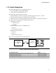
1.10.1.2 Auxiliary Line In Connector
A 1 x 4-pin ATAPI-style connector connects the left and right channel signals of an internal audio
device to the audio subsystem.
For information about Refer to
The location of the auxiliary line in connector Figure 13, page 62
The signal names of the auxiliary line in connector Table 26, page 64
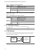
1.10.1.3 ATAPI CD-ROM Audio Connector
A 1 x 4-pin ATAPI-style connector connects an internal ATAPI CD-ROM drive to the audio
mixer.
For information about Refer to
The location of the ATAPI CD-ROM connector Figure 13, page 62
The signal names of the ATAPI CD-ROM connector Table 28, page 64
1.10.2 Audio Subsystem Software
Audio software and drivers are available from Intel’s World Wide Web site.
For information about Refer to
Obtaining audio software and drivers Section 1.3, page 19