
Datasheet

Technical Reference
69
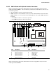
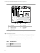
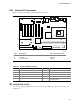
2.8.3 External I/O Connectors
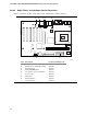
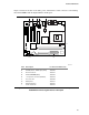
Figure 17 shows the locations of the external I/O connectors.
OM13580
7
10
2
1
9
8
2
1
1
3
A
B
C
Item Description For more information see:
A Auxiliary front panel power/sleep/message-waiting LED Table 39
B Front panel Table 36
C Front panel USB Table 35
Figure 17. External I/O Connectors
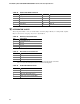
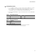
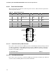
Table 35. Front Panel USB Connector
Pin Signal Name Pin Signal Name
1 USB_FNT_PWR 2 USB_FNT_PWR
3 USB_FNTA# 4 USB_FNTB#
5 USB_FNTA 6 USB_FNTB
7 Ground 8 Ground
9 Key 10 USB_FP_OC (USB front panel
overcurrent signal)
#
INTEGRATOR’S NOTE
Use only a front panel USB connector that conforms to the USB 2.0 specification for high-speed
USB devices.