
Datasheet

Intel Desktop Board D865GBF/D865GLC Technical Product Specification
80
2.8.3.1 Auxiliary Front Panel Power/Sleep/Message-Waiting LED Connector
Pins 1 and 3 of this connector duplicate the signals on pins 2 and 4 of the front panel connector.
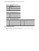
Table 37. Auxiliary Front Panel Power/Sleep/Message-Waiting LED Connector
Pin Signal Name In/Out Description
1 HDR_BLNK_GRN Out Front panel green LED
2 Not connected
3 HDR_BLNK_YEL Out Front panel yellow LED
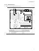
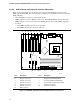
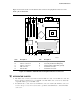
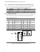
2.8.3.2 Front Panel Connector
This section describes the functions of the front panel connector. Table 38 lists the signal names
of the front panel connector. Figure 24 is a connection diagram for the front panel connector.
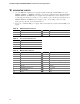
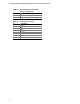
Table 38. Front Panel Connector
Pin Signal In/Out Description Pin Signal In/Out Description
Hard Drive Activity LED Power LED
1 HD_PWR Out Hard disk LED pull-up
(750 Ω) to +5 V
2 HDR_BLNK_
GRN
Out Front panel green
LED
3 HAD# Out Hard disk active LED 4 HDR_BLNK_
YEL
Out Front panel yellow
LED
Reset Switch On/Off Switch
5 Ground Ground 6 FPBUT_IN In Power switch
7 FP_RESET# In Reset switch 8 Ground Ground
Power Not Connected
9 +5 V Power 10 N/C Not connected
Single-colored
Power LED
OM16110
8
6
4
2
9
7
5
3
1
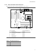
Hard Drive
Activity LED
Reset
Switch
+5 V DC
N/C
Power
Switch
Dual-colored
Power LED
Figure 24. Connection Diagram for Front Panel Connector