
Datasheet


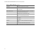

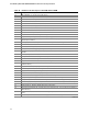
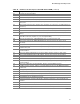
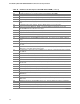
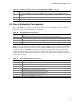

Table Of Contents
- Intel® Desktop Boards D915GEV/D915GRF Technical Product Specification
- Revision History / Disclaimer
- Preface
- Contents
- 1 Product Description
- 1.1 PCI Bus Terminology Change
- 1.2 Overview
- 1.3 Online Support
- 1.4 Processor
- 1.5 System Memory
- 1.6 Intel® 915G Chipset
- 1.7 PCI Express Connectors
- 1.8 I/O Controller
- 1.9 Audio Subsystem
- 1.10 LAN Subsystem
- 1.11 Hardware Management Subsystem
- 1.12 Power Management
- 1.12.1 ACPI
- 1.12.2 Hardware Support
- 1.12.2.1 Power Connector
- 1.12.2.2 Fan Connectors
- 1.12.2.3 LAN Wake Capabilities
- 1.12.2.4 Instantly Available PC Technology
- 1.12.2.5 Resume on Ring
- 1.12.2.6 Wake from USB
- 1.12.2.7 Wake from PS/2 Devices
- 1.12.2.8 PME# Signal Wake-up Support
- 1.12.2.9 WAKE# Signal Wake-up Support
- 1.12.2.10 +5 V Standby Power Indicator LED
- 1.13 Trusted Platform Module
- 1.13.1 System Requirements
- 1.13.2 Warning of Potential Data Loss
- 1.13.3 Security Precautions
- 1.13.4 Trusted Platform Module Ownership
- 1.13.5 Enabling the Trusted Platform Module
- 1.13.6 Assuming Trusted Platform Module Ownership
- 1.13.7 Recovery Procedures
- 1.13.8 Clearing Trusted Platform Module Ownership
- 1.13.9 Software Support
- 2 Technical Reference
- 2.1 Introduction
- 2.2 Memory Resources
- 2.3 DMA Channels
- 2.4 Fixed I/O Map
- 2.5 PCI Configuration Space Map
- 2.6 Interrupts
- 2.7 PCI Conventional Interrupt Routing Map
- 2.8 Connectors
- 2.8.1 Back Panel Connectors
- 2.8.2 Component-side Connectors
- 2.9 Jumper Block
- 2.10 Mechanical Considerations
- 2.11 Electrical Considerations
- 2.12 Thermal Considerations
- 2.13 Reliability
- 2.14 Environmental
- 2.15 Regulatory Compliance
- 3 Overview of BIOS Features
- 4 Error Messages and Beep Codes

Intel Desktop Board D915GEV/D915GRF Technical Product Specification
100
Table 52 describes the lower nibble of the high byte and indicates the bus on which the routines are
being executed.
Table 52. Lower Nibble High Byte Functions
Value Description
0 Generic DIM (Device Initialization Manager)
1 On-board System devices
2 ISA devices
3 EISA devices
4 ISA PnP devices
5 PCI devices
4.4 Speaker
A 47
inductive speaker is mounted on the board. The speaker provides audible error code (beep
code) information during POST.
For information about Refer to
The location of the onboard speaker Figure 1, page 14
4.5 BIOS Beep Codes
Whenever a recoverable error occurs during POST, the BIOS displays an error message describing
the problem (see Table 53). The BIOS also issues a beep code (one long tone followed by two
short tones) during POST if the video configuration fails (a faulty video card or no card installed)
or if an external ROM module does not properly checksum to zero.
An external ROM module (for example, a video BIOS) can also issue audible errors, usually
consisting of one long tone followed by a series of short tones. For more information on the beep
codes issued, check the documentation for that external device.
There are several POST routines that issue a POST terminal error and shut down the system if they
fail. Before shutting down the system, the terminal-error handler issues a beep code signifying the
test point error, writes the error to I/O port 80h, attempts to initialize the video and writes the error
in the upper left corner of the screen (using both monochrome and color adapters). If POST
completes normally, the BIOS issues one short beep before passing control to the operating
system.
Table 53. Beep Codes
Beep Description
1 CPU error
3 Memory error
6 System failure
7 System failure
8 Video error