
Datasheet

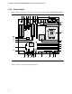
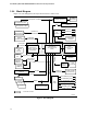


Table Of Contents
- Intel® Desktop Boards D915GEV/D915GRF Technical Product Specification
- Revision History / Disclaimer
- Preface
- Contents
- 1 Product Description
- 1.1 PCI Bus Terminology Change
- 1.2 Overview
- 1.3 Online Support
- 1.4 Processor
- 1.5 System Memory
- 1.6 Intel® 915G Chipset
- 1.7 PCI Express Connectors
- 1.8 I/O Controller
- 1.9 Audio Subsystem
- 1.10 LAN Subsystem
- 1.11 Hardware Management Subsystem
- 1.12 Power Management
- 1.12.1 ACPI
- 1.12.2 Hardware Support
- 1.12.2.1 Power Connector
- 1.12.2.2 Fan Connectors
- 1.12.2.3 LAN Wake Capabilities
- 1.12.2.4 Instantly Available PC Technology
- 1.12.2.5 Resume on Ring
- 1.12.2.6 Wake from USB
- 1.12.2.7 Wake from PS/2 Devices
- 1.12.2.8 PME# Signal Wake-up Support
- 1.12.2.9 WAKE# Signal Wake-up Support
- 1.12.2.10 +5 V Standby Power Indicator LED
- 1.13 Trusted Platform Module
- 1.13.1 System Requirements
- 1.13.2 Warning of Potential Data Loss
- 1.13.3 Security Precautions
- 1.13.4 Trusted Platform Module Ownership
- 1.13.5 Enabling the Trusted Platform Module
- 1.13.6 Assuming Trusted Platform Module Ownership
- 1.13.7 Recovery Procedures
- 1.13.8 Clearing Trusted Platform Module Ownership
- 1.13.9 Software Support
- 2 Technical Reference
- 2.1 Introduction
- 2.2 Memory Resources
- 2.3 DMA Channels
- 2.4 Fixed I/O Map
- 2.5 PCI Configuration Space Map
- 2.6 Interrupts
- 2.7 PCI Conventional Interrupt Routing Map
- 2.8 Connectors
- 2.8.1 Back Panel Connectors
- 2.8.2 Component-side Connectors
- 2.9 Jumper Block
- 2.10 Mechanical Considerations
- 2.11 Electrical Considerations
- 2.12 Thermal Considerations
- 2.13 Reliability
- 2.14 Environmental
- 2.15 Regulatory Compliance
- 3 Overview of BIOS Features
- 4 Error Messages and Beep Codes
Intel Desktop Board D915GEV/D915GRF Technical Product Specification
16
1.2.4 Block Diagram
Figure 2 is a block diagram of the major functional areas of the boards.
Intel 915G Chipset
Intel 82801FB
I/O Controller Hub
(ICH6)
Intel 82915G
Graphics and
Memory Controller
Hub (GMCH)
4 Mbit
Firmware Hub
(FWH)
System Bus
(800/533 MHz)
LGA775
Processor Socket
Parallel ATA
IDE Connector
Diskette Drive
Connector
LPC Bus
I/O
Controller
PS/2 Keyboard
PS/2 Mouse
Parallel Port
Serial Ports
Parallel ATA
IDE Interface
LPC Bus
Hardware Monitoring
and Fan Control ASIC
OM16995
Audio
Codec
Retasking Jack F [Port 2]
Line Out/Retasking Jack D
CD-ROM (optional)
Retasking Jack E [Port 1]
LAN
Connector
PCI Express
x16 Interface
PCI Express
x16
Connector
= connector or socket
PCI Bus
SMBus
High Definition Audio Link
PCI Slot 1
PCI Slot 2
PCI Slot 3
PCI Slot 4
Mic In/Retasking Jack B
Line In/Retasking Jack C
S/PDIF (optional)
DMI Interconnect
10/100
LAN PLC
(Optional)
Serial ATA IDE
Connectors (4)
Serial ATA
IDE Interface
TPM Component
(Optional)
LPC Bus
LAN Connect
Interface
Dual-Channel
Memory Bus
SMBus
VGA
Port
Display Interface
Channel A
DIMMs (2)
Channel B
DIMMs (2)
PCI Bus
IEEE-1394a Connectors
(Optional)
USB
Back Panel/Front Panel
USB Ports
PCI Express x1 Slot 1
PCI Express x1 Slot 2
LAN
Connector
Gigabit Ethernet
Controller (Optional)
PCI Express x1 Interface
Figure 2. Block Diagram