
Datasheet

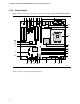


Table Of Contents
- Intel® Desktop Boards D915GEV/D915GRF Technical Product Specification
- Revision History / Disclaimer
- Preface
- Contents
- 1 Product Description
- 1.1 PCI Bus Terminology Change
- 1.2 Overview
- 1.3 Online Support
- 1.4 Processor
- 1.5 System Memory
- 1.6 Intel® 915G Chipset
- 1.7 PCI Express Connectors
- 1.8 I/O Controller
- 1.9 Audio Subsystem
- 1.10 LAN Subsystem
- 1.11 Hardware Management Subsystem
- 1.12 Power Management
- 1.12.1 ACPI
- 1.12.2 Hardware Support
- 1.12.2.1 Power Connector
- 1.12.2.2 Fan Connectors
- 1.12.2.3 LAN Wake Capabilities
- 1.12.2.4 Instantly Available PC Technology
- 1.12.2.5 Resume on Ring
- 1.12.2.6 Wake from USB
- 1.12.2.7 Wake from PS/2 Devices
- 1.12.2.8 PME# Signal Wake-up Support
- 1.12.2.9 WAKE# Signal Wake-up Support
- 1.12.2.10 +5 V Standby Power Indicator LED
- 1.13 Trusted Platform Module
- 1.13.1 System Requirements
- 1.13.2 Warning of Potential Data Loss
- 1.13.3 Security Precautions
- 1.13.4 Trusted Platform Module Ownership
- 1.13.5 Enabling the Trusted Platform Module
- 1.13.6 Assuming Trusted Platform Module Ownership
- 1.13.7 Recovery Procedures
- 1.13.8 Clearing Trusted Platform Module Ownership
- 1.13.9 Software Support
- 2 Technical Reference
- 2.1 Introduction
- 2.2 Memory Resources
- 2.3 DMA Channels
- 2.4 Fixed I/O Map
- 2.5 PCI Configuration Space Map
- 2.6 Interrupts
- 2.7 PCI Conventional Interrupt Routing Map
- 2.8 Connectors
- 2.8.1 Back Panel Connectors
- 2.8.2 Component-side Connectors
- 2.9 Jumper Block
- 2.10 Mechanical Considerations
- 2.11 Electrical Considerations
- 2.12 Thermal Considerations
- 2.13 Reliability
- 2.14 Environmental
- 2.15 Regulatory Compliance
- 3 Overview of BIOS Features
- 4 Error Messages and Beep Codes
Product Description
19
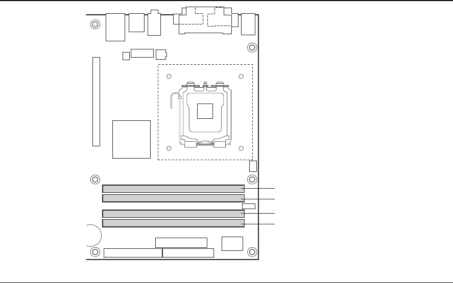
1.5.1 Memory Configurations
The Intel 82915G GMCH supports two types of memory organization:
•
Dual channel (Interleaved) mode. This mode offers the highest throughput for real world
applications. Dual channel mode is enabled when the installed memory capacities of both
DIMM channels are equal. Technology and device width can vary from one channel to the
other but the installed memory capacity for each channel must be equal. If different speed
DIMMs are used between channels, the slowest memory timing will be used.
•
Single channel (Asymmetric) mode. This mode is equivalent to single channel bandwidth
operation for real world applications. This mode is used when only a single DIMM is installed
or the memory capacities are unequal. Technology and device width can vary from one
channel to the other. If different speed DIMMs are used between channels, the slowest
memory timing will be used.
Figure 3 illustrates the memory channel and DIMM configuration.
NOTE
The DIMM0 sockets of both channels are blue. The DIMM1 sockets of both channels are black.
OM16667
Channel A, DIMM 0
Channel A, DIMM 1
Channel B, DIMM 0
Channel B, DIMM 1
Figure 3. Memory Channel and DIMM Configuration