Intel® NUC Products NUC11ATKPE /NUC11ATKC4/ NUC11ATKC2/NUC11ATBC4 Technical Product Specification Regulatory Models: NUC11ATK (Kit/Mini PC) NUC11ATB (Board) February 2022 Revision 3.0 Intel NUC NUC11ATKPE, NUC11ATKC4, NUC11ATKC2, and NUC11ATBC4 may contain design defects or errors known as errata that may cause the product to deviate from published specifications.
Intel NUC Kit/Mini PC NUC11AT{X} Technical Product Specification Revision History 1.1 Revision Revision History Date 1.0 First release of Intel NUC Products NUC11ATKPE, NUC11ATKC4, NUC11ATKC2, and NUC11ATBC4 Technical Product Specification December 2021 2.0 Updated SKUs and Table of Contents January 2022 3.0 Updated SKU & Processor Details February 2022 Disclaimer This product specification applies to only the standard Intel NUC Board, Kit or System with BIOS identifier ATJSLCPX.
Preface This Technical Product Specification (TPS) specifies the board layout, components, connectors, power and environmental requirements, and the BIOS for Intel® NUC Kits, Mini PCs, and Boards NUC11ATKPE, NUC11ATKC4, NUC11ATKC2, and NUC11ATBC4 Intended Audience The TPS is intended to provide detailed, technical information about Intel® NUC Kits, Mini PCs, and Boards NUC11ATKPE, NUC11ATKC4, NUC11ATKC2, and NUC11ATBC4 and its components to the vendors, system integrators, and other engineers and technicia
Intel NUC Kit/Mini PC NUC11AT{X} Technical Product Specification Other Common Notation vi # Used after a signal name to identify an active-low signal (such as USBP0#) GB Gigabyte (1,073,741,824 bytes) GB/s Gigabytes per second Gb/s Gigabits per second KB Kilobyte (1024 bytes) Kb Kilobit (1024 bits) kb/s 1000 bits per second MB Megabyte (1,048,576 bytes) MB/s Megabytes per second Mb Megabit (1,048,576 bits) Mb/s Megabits per second TDP Thermal Design Power xxh An address or data v
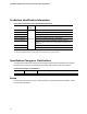
Board Identification Information Basic Intel® NUC Board NUC11ATBC4 Identification Information AA Revision BIOS Revision Notes M62467-xxx ATJSLCPX.vvvv.yyyy.dddd.tttt 1,2,3 Notes: 1. Where, v = version, y = year, d = date, t = time 2. The AA number is found on a small label on the SO-DIMM sockets. 3.
Intel NUC Kit/Mini PC NUC11AT{X} Technical Product Specification Production Identification Information Intel® NUC Products NUC11ATx Identification Information Product Name Intel® NUC Board Differentiating Features BNUC11ATKPE000x Kit with power adapter, “Intel® NUC 11 Essential kit” BNUC11ATKPE0S0x Kit with 64GB eMMC, “Intel® NUC 11 Essential kit” BNUC11ATKC4000x Kit with power adapter, “Intel® NUC 11 Essential kit” BNUC11ATKC40S0x Kit with 64GB eMMC, “Intel® NUC 11 Essential kit” BNUC11ATKC2000
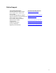
Online Support To Find Information About… Intel NUC Kit/Mini PC NUC11ATKPE, NUC11ATKC4, NUC11ATKC2, and NUC11ATBC4 Intel NUC Board/Kit/Mini PC Support High level details for Intel NUC Kit/Mini PC NUC11ATKPE, NUC11ATKC4, NUC11ATKC2, and NUC11ATBC4 BIOS and driver updates Tested memory Integration information Processor datasheet Regulatory documentation Visit this World Wide Web site: http://www.intel.com/NUC http://www.intel.com/NUCSupport https://ark.intel.com https://downloadcenter.intel.com http://www.
Table of Contents 2 Product Description ............................................................................................... 13 2.1 Overview ...................................................................................................................................................... 13 2.1.1 Summary of Mini PC SKUs ................................................................................................. 13 2.1.2 Summary of Kit and Board SKUs.......................................
Intel NUC Kit/Mini PC NUC11AT{X} Technical Product Specification 6.4 6.5 6.6 Hard Disk Drive Password Security Feature .................................................................................. 35 BIOS Security Features .......................................................................................................................... 36 BIOS Error Messages...............................................................................................................................
Technical Reference 2 Product Description 2.1 Overview 2.1.1 Summary of Mini PC SKUs Product Codes and MM#s for the SKUs below can be found at https://ark.intel.com. Processor Intel® Celeron® N4505 1 AC Cord (C5) US, EU, UK, AU, or No Cord CN RAM Storage OS 4 GB 64 GB eMMC Win 10 Home “WW” refers to worldwide 2.1.2 Summary of Kit and Board SKUs Product Codes and MM#s for the SKUs below can be found at https://ark.intel.com.
Intel NUC Kit/Mini PC NUC11AT{X} Technical Product Specification 2.1.3 Feature Summary Table 1 summarizes the major features of Intel® NUC Products NUC11ATKPE, NUC11ATKC4, NUC11ATKC2, and NUC11ATBC4. Table 1. Feature Summary Form Factor 4.5 inches by 5.25 inches 114mm x 133mm x 35mm for chassis, (including feet) Processor A soldered-down 11th generation Intel® Celeron® N4505 processor with up to a maximum 10 W TDP (if thermal margin is available). • 2.00 GHz base frequency, 2.
Technical Reference Expansion Capabilities • Two ports are implemented via the external back panel connectors (black) • One M.2 connector supporting M.2 2280 or 2242 (key type M) modules • One M.2 connector supporting M.
Intel NUC Kit/Mini PC NUC11AT{X} Technical Product Specification 3 Product Layout 3.1 Board Layout 3.1.1 Board Layout (Bottom) Figure 1 shows the location of the major components on the bottom of Intel® NUC Products NUC11ATKPE, NUC11ATKC4, NUC11ATKC2, and NUC11ATBC4 Figure 1.
Technical Reference Table 3. Components Shown in Figure 1 Item from Figure 2 Description A DC Input Jack Power Button B USB 3.2 gen 1x1 port (blue) C USB 3.2 gen 1x1 port (blue) D Front Panel Header E Microphone Jack F Headset Jack G DDR4 SO-DIMM1 socket H DDR4 SO-DIMM2 socket I Display Port 1.4 Connector J RJ-45 Ethernet Jack K 2x USB 2.0 Ports (Black) L 2x USB 3.2 gen 2x1 (Blue) M HDMI 2.0b Port N DC Input Jack O BIOS Security Jumper P M.
Intel NUC Kit/Mini PC NUC11AT{X} Technical Product Specification 3.1.2 Board Layout (Top) Figure 2 shows the location of the major components on the top side of Intel® NUC Products NUC11ATKPE, NUC11ATKC4, NUC11ATKC2, and NUC11ATBC4. Figure 2. Major Board Components (Top) Table 4.
Technical Reference 3.1.3 Front Panel Figure 3. Front Panel Connectors 3.1.4 Back Panel f Figure 4.
Intel NUC Kit/Mini PC NUC11AT{X} Technical Product Specification 3.1.5 Block Diagram Figure 5.
Technical Reference 4 Feature Descriptions 4.1 System Memory Figure 1 illustrates the memory channel and SO-DIMM configuration. 4.1.1 Intel® NUC Mini PC Memory Information Intel® NUC Mini PC ship with 2 x 4 GB DDR4 2933MHz SODIMMs included. More information about available Intel® NUC Mini PCs NUC11ATK can be found in Section 2.1.1 Summary of Mini PC SKUs. 4.2 Graphics Subsystem Intel® NUC Products NUC11ATKPE, NUC11ATKC4, NUC11ATKC2, and NUC11ATBC4 support Intel® UHD Graphics 4.2.
Intel NUC Kit/Mini PC NUC11AT{X} Technical Product Specification NOTE If the battery and AC power fail, date and time values will be reset and the user will be notified during the POST. When the voltage drops below a certain level, the BIOS Setup program settings stored in CMOS RAM (for example, the date and time) might not be accurate. Replace the battery with an equivalent one. Figure 2 on page 18 shows the location of the battery. 4.3 LAN Subsystem 4.3.
Technical Reference 4.4 Hardware Management Subsystem 4.4.1 Fan Monitoring Fan monitoring can be implemented using third-party software. 4.4.2 System States and Power States Table 6 describes the ACPI states supported by the processor. Table 6. Systems States State Description G0/S0/C0 Full On: CPU operating. Individual devices may be shut to save power. The different CPU operating levels are defined by Cx states.
Intel NUC Kit/Mini PC NUC11AT{X} Technical Product Specification Notes: 1. S4 implies operating system support only. 2. Will not wake from Deep S4/S5. USB S4/S5 Power is controlled by BIOS. USB S5 wake is controlled by BIOS. USB S4 wake is controlled by OS driver, not just BIOS option. 3. Windows Fast startup will block wake from LAN and USB from S5. NOTE The use of these wake-up events from an ACPI state requires an operating system that provides full ACPI support.
Technical Reference 13* VSS4 14* VDD2 15* D1- 16* D1+ 17* VSS5 The board has a full-sized Secure Digital (SD) card reader that supports the Secure Digital eXtended Capacity (SDXC) format, 4.0 specification, UHS-II bus speed. NOTE *Pins 10-17 added with UHS-II v4.0 specification. Not present on all SD cards. Table 9. M.2 2280 Module (Mechanical Key M) Connector Pin Signal Name Pin Signal Name 74 72 3.3V (4A total for pins 74, 72, 70, 18, 16, 14, 12, 4, 2 (0.5A per pin)) 3.
Intel NUC Kit/Mini PC NUC11AT{X} Technical Product Specification 18 3.3V (4A total for pins 74, 72, 70, 18, 16, 14, 12, 4, 2 (0.5A per pin)) 19 PERp2 16 3.3V (4A total for pins 74, 72, 70, 18, 16, 14, 12, 4, 2 (0.5A per pin)) 17 PERn2 14 3.3V (4A total for pins 74, 72, 70, 18, 16, 14, 12, 4, 2 (0.5A per pin)) 15 GND 12 3.3V (4A total for pins 74, 72, 70, 18, 16, 14, 12, 4, 2 (0.5A per pin)) 13 PETp3 10 DAS/DSS# (I/O)/LED1# (I)(0/3.3V) 11 PETn3 8 N/C 9 GND 6 N/C 7 PERp3 4 3.
Technical Reference Blinking Standby Steady Normal operation Table 12. States for a Dual-Color Power LED LED State Description Off Power off Blinking (white) Standby Steady (white) Normal operation NOTE The LED behavior shown in Table 11 is default – other patterns may be set via BIOS setup. 5.1.1.1.4 Power Switch Header Pins 6 and 8 can be connected to a front panel momentary-contact power switch.
Intel NUC Kit/Mini PC NUC11AT{X} Technical Product Specification Figure 7. Location of the BIOS Security Jumper Table 13 describes the jumper settings for the three modes: normal, lockdown, and configuration. Table 13. BIOS Security Jumper Settings 28 Function/Mode Jumper Setting Configuration Normal 1-2 Lockdown 2-3 The BIOS uses current configuration information and passwords for booting.
Technical Reference Configuration 5.1.1.3 None BIOS Recovery Update process if a matching *.cap file is found. Recovery Update can be cancelled by pressing the Esc key. If the Recovery Update was cancelled or a matching *.bio file was not found, a Config Menu will be displayed. The Config Menu consists of the following (followed by the Power Button Menu selections): [1] Suppress this menu until the BIOS Security Jumper is replaced. [2] Clear BIOS User and Supervisor Passwords.
Intel NUC Kit/Mini PC NUC11AT{X} Technical Product Specification Figure 8.
Technical Reference Figure 9 shows the height dimensions of the board. Dimensions are in mm. Figure 9. Board Height Dimensions 5.3 Thermal Considerations CAUTION Failure to ensure appropriate airflow may result in reduced performance of both the processor and/or voltage regulator or, in some instances, damage to the board. All responsibility for determining the adequacy of any thermal or system design remains solely with the system integrator.
Intel NUC Kit/Mini PC NUC11AT{X} Technical Product Specification 5.4 Environmental Table 15 lists the environmental specifications for the board. CAUTION If the external ambient temperature exceeds 35 oC, further thermal testing is required to ensure components do not exceed their maximum operating temperature. Table 15. Environmental Specifications Parameter Specification Temperature Sustained Storage Limits (i.e. warehouse) Short Duration Limits (i.e.
Technical Reference 6 Overview of BIOS Features 6.1 Introduction The board uses an Intel AMI BIOS core that is stored in the Serial Peripheral Interface Flash Memory (SPI Flash) and can be updated through multiple methods (see Section 6.2). The SPI Flash contains the BIOS Setup program, POST, the PCI auto-configuration utility, LAN EEPROM information, and Plug and Play support. The SPI Flash includes a 256 MB flash memory device.
Intel NUC Kit/Mini PC NUC11AT{X} Technical Product Specification NOTE The network can be selected as a boot device. This selection allows booting from the onboard LAN or a network add-in card with a remote boot ROM installed. Pressing the key during POST automatically forces booting from the LAN. To use this key during POST, the User Access Level in the BIOS Setup program’s Security menu must be set to Full. 6.3.
Technical Reference 6.4 [F7] Update BIOS BIOS Update during the BDS phrase. The BIOS will update independent of any OS loading and provides a menu UI accessible during boot up. This is not a recovery tool and will not overwrite a corrupt BIOS or ME firmware. [F9] Remote Assistance Note: Will only be displayed if Remote Assistance is supported.
Intel NUC Kit/Mini PC NUC11AT{X} Technical Product Specification 6.5 BIOS Security Features The BIOS includes security features that restrict access to the BIOS Setup program and who can boot the computer. A Supervisor and User password can be set for the BIOS Setup program and for botting the computer, with the following restrictions: • The Supervisor password gives unrestricted access to view and change all the Setup options in the BIOS Setup program. This is Supervisor Mode.
Technical Reference CMOS Timer Not Set The battery may be losing power. Replace the battery soon. Processor Thermal Trip Processor overheated. Auto RTC Reset The system triggers RTC clear to recover the system back to the normal condition from consecutive boot failure.