Intel® NUC Products NUC8i3BE/NUC8i5BE/NUC8i7BE Technical Product Specification Regulatory Models: NUC8BEK (Short Kit/Mini PC) NUC8BEH (Tall Kit/Mini PC) NUC8BEB (Board) November 2018 Order Number: K15389-003 i
Intel NUC Products NUC8i3BE, NUC8i5BE and NUC8i7BE may contain design defects or errors known as errata that may cause the product to deviate from published specifications. Current characterized errata, if any, are documented in Intel NUC Products NUC8i3BE/NUC8i5BE/NUC8i7BE Specification Update.
Contents Copyright 2018 Intel Corporation. All rights reserved.
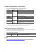
Product Identification Information Intel® NUC Products NUC8i{x}BE{y}{z}1 Identification Information Product Name Intel® NUC Board Differentiating Features Kit with power adapter NUC8i3BEK NUC8i3BEH NUC8i3BEB HDD-capable kit with power adapter NUC8i3BEHXF J72693-303 HDD kit with power adapter, 16GB Intel® Optane™ Module, 1TB HDD, 4GB DDR4-2400 SDRAM[2], Microsoft Windows 10 Home, “Intel® NUC 8 Home, a Mini PC with Windows 10” NUC8i5BEK Kit with power adapter NUC8i5BEH NUC8i5BEB HDD-capable kit w
Contents Preface This Technical Product Specification (TPS) specifies the board layout, components, connectors, power and environmental requirements, and the BIOS for Intel® NUC Board NUC8i3BEB, Intel® NUC Board NUC8i5BEB and Intel® NUC Board NUC8i7BEB.
Other Common Notation vi # Used after a signal name to identify an active-low signal (such as USBP0#) GB Gigabyte (1,073,741,824 bytes) GBps Gigabytes per second Gbps Gigabits per second KB Kilobyte (1024 bytes) Kb Kilobit (1024 bits) kbps 1000 bits per second MB Megabyte (1,048,576 bytes) MBps Megabytes per second Mb Megabit (1,048,576 bits) Mbps Megabits per second TDP Thermal Design Power Xxh An address or data value ending with a lowercase h indicates a hexadecimal value. x.
Contents Contents Revision History ............................................................................................................... ii Disclaimer ..................................................................................................................................................................
1.11.1 Intel® I219V Gigabit Ethernet Controller ..................................................................... 17 1.11.2 LAN Subsystem Software ................................................................................................... 18 1.11.3 RJ-45 LAN Connector with Integrated LEDs .............................................................. 18 1.11.4 Wireless Network Module .................................................................................................. 19 1.
Contents 3.8 3.9 3.7.2 Booting Without Attached Devices (Headless).......................................................... 54 3.7.3 Changing the Default Boot Device during POST ...................................................... 54 3.7.4 Power Button Menu .............................................................................................................. 55 Hard Disk Drive Password Security Feature..................................................................................
Figures Figure 1. Major Board Components (Top) .......................................................................................................... 3 Figure 2. Major Board Components (Bottom) ................................................................................................... 4 Figure 3. Block Diagram.............................................................................................................................................. 6 Figure 4.
Contents Table 15. SATA Power Connector (1.25 mm pitch) ..................................................................................... 33 Table 16. Single-Port Internal USB 2.0 Header (1.25 mm pitch) ........................................................... 33 Table 17. M.2 2280 Module (key type M) Connector .................................................................................. 33 Table 18. Digital Microphone (DMICS) Array Connector (1.25 mm Pitch)......................................
1 Product Description 1.1 Overview 1.1.1 Feature Summary Table 1 summarizes the major features of Intel® NUC Board NUC8i3BEB, Intel® NUC Board NUC8i5BEB and Intel® NUC Board NUC8i7BEB. Table 1. Feature Summary Form Factor 4.0 inches by 4.0 inches (101.60 millimeters by 101.60 millimeters) Processor • A soldered-down 8th generation Intel® Core™ i3-8109U dual-core processor with a maximum 28 W TDP, 3.0 GHz base, 3.
Table 1. Feature Summary (continued) Peripheral Interfaces • One USB 3.1 (Gen 2/10 Gbps) port implemented via the external back panel Type C connector • USB 3.1 (Gen 2/10 Gbps) Type A ports: Two ports are implemented with external front panel connectors (one blue and one orange charging capable) • Two ports are implemented with external back panel connectors (blue) • USB 2.0 ports: • • Two ports via two single-port internal 1x4 1.
Intel NUC Kit Features 1.1.2 Board Layout (Top) Figure 1 shows the location of the major components on the top-side of Intel NUC Board NUC8i3BEB, Intel NUC Board NUC8i5BEB and Intel NUC Board NUC8i7BEB. Figure 1. Major Board Components (Top) Table 2 lists the components identified in Figure 1. Table 2.
1.1.3 Board Layout (Bottom) Figure 2 shows the location of the major components on the bottom-side of Intel NUC Board NUC8i3BEB, Intel NUC Board NUC8i5BEB and Intel NUC Board NUC8i7BEB. Figure 2.
Intel NUC Kit Features Table 3. Components Shown in Figure 2 Item from Figure 2 Description A DC Input Jack B HDMI connector C LAN connector D USB 3.1 ports (blue) E Digital Microphones (DMICs) header F Front Panel header G Intel Dual Band Wireless AC + Bluetooth 9560 module H RGB (HDD) LED header I Micro SDXC slot J SATA power connector (1.25 mm pitch) K M.2 connector (key type M and B+M) for 2242 and 2280 modules L Front panel single-port USB 2.0 header (1.
1.1.4 Block Diagram Figure 3 is a block diagram of the major functional areas of the board. Figure 3.
Intel NUC Kit Features 1.2 Online Support To find information about… Visit this Intel web site: Intel NUC Board NUC8i3BEB, Intel NUC Board NUC8i5BEB, and Intel NUC Board NUC8i7BEB http://www.intel.com/NUC Intel NUC Support http://www.intel.com/NUCSupport Available configurations for Intel NUC Board NUC8i3BEB, Intel NUC Board NUC8i5BEB and Intel NUC Board NUC8i7BEB http://ark.intel.com Product support page NUC8i3BEK https://www.intel.
1.3 Processor One of the following: A soldered-down 8th generation Intel® Core™ i3-8109U dual-core processor with up to a maximum 28 W TDP (if thermal margin is available). • • • • 3.0 GHz base frequency, 3.6 GHz turbo frequency, 4 threads Intel® Iris™ Plus Graphics 655 Integrated memory controller Integrated PCH A soldered-down 8th generation Intel® Core™ i5-8259U quad-core processor with up to a maximum 28 W TDP (if thermal margin is available). • • • • 2.3 GHz base frequency, 3.
Intel NUC Kit Features NOTE To be fully compliant with all applicable DDR SDRAM memory specifications, the board should be populated with SO-DIMMs that support the Serial Presence Detect (SPD) data structure. This allows the BIOS to read the SPD data and program the chipset to accurately configure memory settings for optimum performance.
Figure 4 illustrates the memory channel and SO-DIMM configuration. Figure 4.
Intel NUC Kit Features 1.5 Processor Graphics Subsystem The Intel NUC Boards NUC8i3BEB, NUC8i5BEB and NUC8i7BEB support graphics through Intel Iris™ Plus Graphics 655. 1.5.1 Integrated Graphics The board supports integrated graphics via the processor. 1.5.1.1 Intel® High Definition (Intel® HD) Graphics The Intel Iris™ Plus graphics controller features the following: • API support ― Direct3D* 2015, Direct3D 11.2, Direct3D 11.1, Direct3D 9, Direct3D 10, Direct2D ― OpenGL* 4.5 support ― OpenCL* 2.
1.5.1.3 High Definition Multimedia Interface* (HDMI*) HDMI is supported through a MegaChips MCDP2800-BCT DisplayPort 1.2a to HDMI 2.0 Level Shifter/Protocol Converter (LSPCON). The HDMI port supports standard, enhanced, or high definition video, plus multi-channel digital audio on a single cable. The port is compatible with all ATSC and DVB HDTV standards and supports eight full range channels at 24-bit/192 kHz audio of lossless audio formats.
Intel NUC Kit Features 1.5.1.5 Multiple DisplayPort and HDMI Configurations Multiple DisplayPort and HDMI configurations feature the following: Single HDMI 2.0a with 4K @ 60 Hz support Single DisplayPort 1.
1.6 LPCM, 192kHz/24 bit, 8 channel Yes Yes Dolby True HD, DTS-HD Master Audio* (Lossless Blu-ray Disc Audio Format) Yes Yes USB The USB port arrangement is as follows: • • USB 3.1 Gen 2 (10 Gbps) Type C port implemented via the external back panel Type C connector (maximum current is 3A) USB 3.1 Gen 2 (10 Gbps) Type A ports (maximum current is 900 mA for each blue port, 1.
Intel NUC Kit Features 1.7.1 AHCI Mode The board supports AHCI storage mode. NOTE In order to use AHCI mode, AHCI must be enabled in the BIOS. Microsoft* Windows* 10 includes the necessary AHCI drivers without the need to install separate AHCI drivers during the operating system installation process; however, it is always good practice to update the AHCI drivers to the latest available by Intel. 1.7.
1.8 Thunderbolt 3 The boards support Thunderbolt™ 3 with up to 40 Gbps of data throughput, one 4k (60Hz) monitor output, USB3.1 (Gen 2) connection and charging capabilities up to 5V at 3A via the back panel USB Type C connector. Item A in Figure 11 shows the location of the rear panel USB Type C port. 1.9 For information about Refer to Compatible Thunderbolt™ 3 devices https://www.intel.com/content/www/us/en/support/article s/000027966.html Thunderbolt™ 3 information http://www.intel.
Intel NUC Kit Features Pin Number Pin Name Description 1 2 3 4 Tip Ring Ring Sleeve Left Audio Out Right Audio Out Common/Ground Audio In/MIC Figure 5. 4-Pin 3.5 mm (1/8 inch) Audio Jack Pin Out NOTE The analog circuit of the front panel audio connector is designed to power headphones or amplified speakers only. Poor audio quality occurs if passive (nonamplified) speakers are connected to this output. 1.10.1 Audio Subsystem Software Audio software and drivers are available from Intel’s web site.
Flow control support compliant with the 802.3X specification as well as the specific operation of asymmetrical flow control defined by 802.3z VLAN support compliant with the 802.3q specification Supports Jumbo Frames (up to 9 kB) ― IEEE 1588 supports (Precision Time Protocol) • • • MAC address filters: perfect match unicast filters, multicast hash filtering, broadcast filter, and promiscuous mode Preboot eXecution Environment (PXE): support in both Legacy and UEFI modes.
Intel NUC Kit Features 1.11.4 Wireless Network Module The Intel Dual Band Wireless-AC 9560 module provides hi-speed wireless connectivity with the following capabilities: Compliant with IEEE 802.11a/b/g/n/ac, 802.11d, 802.11e, 802.11h, 802.11i, 802.11w, 802.11r, 802.11k specifications Wi-Fi CERTIFIED* a/b/g/n/ac with wave 2 features, WMM*, WMM-PS*, WPA*, WPA2*, WPS2* Maximum bandwidth of 1.73 Gbps Dual Mode Bluetooth® 5 Downlink MU-MIMO 2x2: two Transmit and two Receive streams 160 MHz channels (2.
Item Description A Thermal solution B Processor fan header Figure 7. Thermal Solution and Fan Header 1.
Intel NUC Kit Features 1.13.1 ACPI ACPI gives the operating system direct control over the power management and Plug and Play functions of a computer. The use of ACPI with this board requires an operating system that provides full ACPI support.
1.13.1.1 System States and Power States Under ACPI, the operating system directs all system and device power state transitions. The operating system puts devices in and out of low-power states based on user preferences and knowledge of how devices are being used by applications. Devices that are not being used can be turned off. The operating system uses information from applications and user settings to put the system as a whole into a low-power state.
Intel NUC Kit Features 1.13.1.2 Wake-up Devices and Events Table 12 lists the devices or specific events that can wake the computer from specific states. Table 12.
1.13.2.1 Power Input When resuming from an AC power failure, the computer returns to the power state it was in before power was interrupted (on or off). The computer’s response can be set using the Last Power State feature in the BIOS Setup program’s Boot menu. 1.13.2.2 Instantly Available PC Technology Instantly Available PC technology enables the board to enter the ACPI S3 (Suspend-to-RAM) sleep-state.
Intel NUC Kit Features CAUTION If AC power has been switched off and the standby power indicator is still lit, disconnect the power cord before installing or removing any devices connected to the board. Failure to do so could damage the board and any attached devices. Figure 8.
1.13.3 Microsoft Modern Standby Support Intel NUC Products NUC8i3BE/NUC8i5BE/NUC8i7BE support Windows* 10 Modern Standby, Microsoft’s implementation of ACPI low power S0 idle. This allows the system to reduce power consumption and only wake when necessary, as for system maintenance tasks or user intervention. Modern Standby is required for Wake-on-Voice capability. NOTES You cannot switch between ACPI S3 and Modern Standby.
Intel NUC Kit Features 1.14.2 Intel® Platform Trust Technology Intel® Platform Trust Technology (Intel® PTT) is a platform functionality for credential storage and key management. Intel® PTT supports Microsoft* BitLocker* Drive Encryption for hard drive encryption and supports all Microsoft requirements for firmware Trusted Platform Module (fTPM) 2.0 for client computers. NOTE Support for fTPM version 2.0 requires a UEFI-enabled operating system, such as Microsoft* Windows* 10.
2 Technical Reference 2.1 Memory Resources 2.1.1 Addressable Memory The board utilizes a maximum of 32 GB of addressable system memory. Typically the address space that is allocated for PCI Conventional bus add-in cards, PCI Express configuration space, BIOS (SPI Flash device), and chipset overhead resides above the top of DRAM (total system memory).
Intel NUC Kit Features This section describes the board’s connectors and headers. The connectors and headers can be divided into these groups: • • 2.2.1 Front panel I/O connectors Back panel I/O connectors Front Panel Connectors Figure 9 shows the location of the front panel connectors for the board. Item Description A Front panel power button B CIR C Front panel Stereo microphone/headphone jack D USB 3.1 (Gen 2) ports (orange charging capable) E USB 3.
2.2.3 Headers and Connectors (Top) Figure 11 shows the location of the headers and connectors on the top-side of the board. Figure 11. Headers and Connectors (Top) Table 13 lists the headers and connectors identified in Figure 11. Table 13.
Intel NUC Kit Features 2.2.4 Connectors and Headers (Bottom) Figure 12 shows the locations of the connectors and headers on the bottom-side of the board. Figure 12.
Table 14 lists the connectors and headers identified in Figure 12. Table 14. Connectors and Headers Shown in Figure 12 32 Item from Figure 12 Description A Digital microphone array connector B Front panel header C RGB LED connector D Micro SDXC slot E SATA power connector (1.25 mm pitch) F M.2 connector (key type M and B+M) for 2242 and 2280 modules G Front panel single-port USB 2.0 header (1.25 mm pitch) H Front panel single-port USB 2.0 header (1.25 mm pitch) I SATA 6.
Intel NUC Kit Features 2.2.4.1 Signal Tables for the Connectors and Headers Table 15. SATA Power Connector (1.25 mm pitch) Pin Signal Name 1 +5 V 2 +5 V 3 +3.3 V 4 GND 5 GND NOTE Connector is Molex* part number 53398-0571, 1.25 mm pitch PicoBlade* header, surface mount, vertical, lead-free, 5 circuits. Table 16. Single-Port Internal USB 2.0 Header (1.25 mm pitch) Pin Signal Name Pin Signal Name 1 +5 V DC 2 D- 3 D+ 4 Ground See section 2.2.4.7 for more information on USB 2.
Table 17. M.2 2280 Module (key type M) Connector (continued) Pin Signal Name Pin Signal Name 54 PEWAKE# (I/O)(0/3.3V) or N/C 55 REFCLKP 52 CLKREQ# (I/O)(0/3.3V) or N/C 53 REFCLKN 50 PERST# (O)(0/3.
Intel NUC Kit Features NOTE Connector is Aces part number 50273-0047C-002, 1.25 mm pitch header, surface mount, vertical, lead-free, 4 circuits. Table 19. RGB LED Connector (1.25 mm Pitch) Pin Signal Name 1 +5VSB 2 Red HDD LED 3 Green HDD LED 4 Blue HDD LED See section 2.2.4.10 for more information on the RGB LED connector. NOTE Connector is Aces part number 50273-0047C-002, 1.25 mm pitch header, surface mount, vertical, lead-free, 4 circuits. Table 20. CEC Header (1.
2.2.4.2 Add-in Card Connectors The board supports M.2 2242 and 2280 (key type M) modules. • Supports M.2 SSD SATA drives ― Maximum bandwidth is approximately 540 MBps • Supports M.2 SSD Gen 3 PCIe AHCI and NVMe drives (PCIe x1, x2, and x4) ― Using PCIe x4 M.2 SSD maximum bandwidth is approximately 4000 MBps 2.2.4.3 USB Type C connector The board has several features that are supported via the USB Type C connector. • Supports USB 3.1 Gen 2.
Intel NUC Kit Features 3 HDD_LED# [Out] Hard disk activity LED 4 POWER_LED_ALT [Out] Front panel LED (alt color) 5 GROUND Ground 6 POWER_SWITCH# [In] Power switch 7 RESET_SWITCH# [In] Reset switch 8 GROUND Ground 9 +5V_DC Power 10 Key No pin Figure 13. Connection Diagram for Front Panel Header (2.0 mm Pitch) 2.2.4.4.1 Hard Drive Activity LED Pins Pins 1 and 3 can be connected to an LED to provide a visual indicator that data is being read from or written to a hard drive.
Primary color steady (Blue) Normal operation NOTE The LED behavior shown in Table 23 is default – other patterns may be set via BIOS setup. 2.2.4.4.4 Power Switch Pins Pins 6 and 8 can be connected to a front panel momentary-contact power switch. The switch must pull the SW_ON# pin to ground for at least 50 ms to signal the power supply to switch on or off. (The time requirement is due to internal debounce circuitry on the board.
Intel NUC Kit Features NOTE It is recommended that you disable this feature (via BIOS option) when using an AC-DC adapter greater than 90 W. 2.2.4.7 Internal USB 2.0 Single-Port Header (1.25 mm Pitch) Figure 14 is a connection diagram for the internal USB header. NOTE • • The +5 V DC power on the USB header is fused. Use only an internal USB connector that conforms to the USB 2.0 specification for high-speed USB devices. Figure 14. Connection Diagram for the Internal USB 2.0 Single-Port Header (1.
2.2.4.9 Consumer Electronics Control (CEC) Header The board contains two mutually-exclusive methods for controlling HDMI CEC devices: • External CEC adaptor connected via CEC connector (item K in Figure 12; pinout in Table 20) • Onboard CEC control from the embedded controller via HDMI cable and BIOS setup. Expected behavior is provided in Table 26 below. Table 26.
Intel NUC Kit Features 2.2.4.11 Digital Microphone Array The digital microphone array consists of dual front facing digital microphones located on either side of the front panel to minimize acoustic interference. The digital microphone array is intended to be used with a digital assistant like Microsoft’s Cortana*. Item A in Figure 12 shows the location of the digital microphone array connector. Table 18 lists the signal names of the DMIC connector.
Table 28 lists the settings for the jumper. Table 28. BIOS Security Jumper Settings Function/Mode Jumper Setting Configuration Normal 1-2 The BIOS uses current configuration information and passwords for booting. Lockdown 2-3 The BIOS uses current configuration information and passwords for booting, except: • All POST Hotkeys are suppressed (prompts are not displayed and keys are not accepted. For example, F2 for Setup, F10 for the Boot Menu). • Power Button Menu is not available (see Section 3.7.
Intel NUC Kit Features 2.4 Mechanical Considerations 2.4.1 Form Factor The board is designed to fit into a custom chassis. Figure 17 illustrates the mechanical form factor for the board. Dimensions are given in inches [millimeters]. Figure 17.
Figure 18 shows the height dimensions of the board. Figure 18. Board Height Dimensions 2.4.2 Weights Table 29. Select Weights lists select weights of boards and kits. Table 29. Select Weights Item Weight (in kg) Board with Thermal Solution 0.2 Short Kit (includes Board Assembly) 0.47 Tall Kit (includes Board Assembly) 0.58 2.5 Electrical Considerations 2.5.
Intel NUC Kit Features 2.6 Thermal Considerations CAUTION A chassis with a maximum temperature of 50 oC at the processor fan inlet is recommended. If the internal ambient temperature exceeds 50 oC, further thermal testing is required to ensure components do not exceed their maximum case temperature. CAUTION Failure to ensure appropriate airflow may result in reduced performance of both the processor and/or voltage regulator or, in some instances, damage to the board.
Figure 19 shows the locations of the localized high temperature zones. Item Description A Thermal solution B Processor voltage regulator area Figure 19.
Intel NUC Kit Features A thermal pad has been installed for the bottom of the chassis to improve the thermal performance when using M.2 devices that operate at higher temperatures. If the thermal pad ever needs to be replaced, Figure 20 shows the installation area of the thermal pad for Intel NUC Kit NUC8i3BEK and Intel NUC Kit NUC8i5BEK. Item Description A Thermal Pad B Thermal Pad Installation Area Figure 20.
Figure 21 shows the installation area of the thermal pad for Intel NUC Kit NUC8i3BEH, Intel NUC Kit NUC8i5BEH and Intel NUC Kit NUC8i7BEH. Item Description A Thermal Pad B Thermal Pad Installation Area Figure 21.
Intel NUC Kit Features Table 31. Thermal Considerations for Components provides maximum case temperatures for the components that are sensitive to thermal changes. The operating temperature, current load, or operating frequency could affect case temperatures. Maximum case temperatures are important when considering proper airflow to cool the board. Table 31.
2.7 Reliability The Mean Time between Failures (MTBF) predictions are calculated using component and subassembly random failure rates. The calculation is based on the Telcordia SR-332 Issue 2, Method I, Case 3, 55 ºC ambient. The MTBF prediction is used to estimate repair rates and spare parts requirements. The MTBF for Intel NUC8i3BEB board is 62,994 hours. The MTBF for Intel NUC8i5BEB board is 63,369 hours. The MTBF for Intel NUC8i7BEB board is 64,998 hours. 2.8 Environmental Table 33.
Intel NUC Kit Features 3 Overview of BIOS Features 3.1 Introduction The board uses Intel Visual BIOS that is stored in the Serial Peripheral Interface Flash Memory (SPI Flash) and can be updated using a disk-based program. The SPI Flash contains the Visual BIOS Setup program, POST, the PCI auto-configuration utility, embedded controller (EC) firmware, LAN EEPROM information, and Plug and Play support. The BIOS displays a message during POST identifying the type of BIOS and a revision code.
3.4 Legacy USB Support Legacy USB support enables USB devices to be used even when the operating system’s USB drivers are not yet available. Legacy USB support is used to access the BIOS Setup program, and to install an operating system that supports USB. By default, Legacy USB support is set to Enabled. Legacy USB support operates as follows: 1. When you first apply power to the computer, legacy support is disabled. 2. POST begins. 3.
Intel NUC Kit Features 3.5.1 Language Support The BIOS Setup program and help messages are supported in US English. Check the Intel web site for support. 3.6 BIOS Recovery It is unlikely that anything will interrupt a BIOS update; however, if an interruption occurs, the BIOS could be damaged. Table 34. Acceptable Drives/Media Types for BIOS Recovery lists the drives and media types that can and cannot be used for BIOS recovery. The BIOS recovery media does not need to be made bootable. Table 34.
3.7 Boot Options In the BIOS Setup program, the user can choose to boot from a hard drive, optical drive, removable drive, or the network. The default setting is for the optical drive to be the first boot device, the hard drive second, removable drive third, and the network fourth. NOTE Optical drives are not supported by the onboard SATA connectors. Optical drives are supported only via the USB interfaces. If the optical drive is not bootable, it will be ignored during the POST process. 3.7.
Intel NUC Kit Features 3.7.4 Power Button Menu As an alternative to normal POST Hotkeys, the user can use the power button to access a menu. The Power Button Menu is accessible via the following sequence: 1. System is in S4/S5 (soft off); will not work if system is in G3 (after “no power” state) 2. User pushes the power button and holds it down for 3 seconds 3. The front panel power button LED will change from Blue to Amber then the user can release the power button. 4.
3.8 Hard Disk Drive Password Security Feature The Hard Disk Drive Password Security feature blocks read and write accesses to the hard disk drive until the correct password is given. Hard Disk Drive Passwords are set in BIOS SETUP and are prompted for during BIOS POST. For convenient support of S3 resume, the system BIOS will automatically unlock drives on resume from S3. Valid password characters are A-Z, a-z, and 0-9. Passwords may be up to 19 characters in length.
Intel NUC Kit Features Currently, there is no industry standard for implementing Hard Disk Drive Password Security on AHCI or NVME drives. Hard drive encryption can still be implemented and does not require Hard Disk Drive Password Security. 3.9 BIOS Security Features The BIOS includes security features that restrict access to the BIOS Setup program and who can boot the computer.
4 Error Messages and Blink Codes 4.1 Front-panel Power LED Blink Codes Whenever a recoverable error occurs during POST, the BIOS causes the board’s front panel power LED to blink an error message describing the problem (see Table 38. Front-panel Power LED Blink Codes). Table 38. Front-panel Power LED Blink Codes 4.2 Type Pattern Note Power-on Solid on primary color. Indicates S0 state. Default to On; can be disabled via BIOS Setup S3 Standby Blink alternate color .25 seconds on, .
Intel NUC Kit Features 5 Intel NUC Kit Features 5.1 Chassis Front Panel Features See the Product Identification Information section on page iv to identify Intel NUC Boards and their respective kit or system. Figure 22 and Figure 23 shows the location of the features located on or near the front of the chassis. Figure 22. Intel NUC Kit NUC8i3BEH/NUC8i5BEH/NUC8i7BEH Features – Front Table 40. Components Shown in Figure 22 lists the components identified in Figure 22. Table 40.
Figure 23. Intel NUC Kit NUC8i3BEK/NUC8i5BEK Features – Front Table 41. Components Shown in Figure 23 lists the components identified in Figure 23. Table 41. Components Shown in Figure 23 Item from Figure 23 Description Kensington* Anti-Theft Key Lock Hole Micro SDXC Card Reader Digital Microphone Array Power Switch and Power LED Consumer Infrared Sensor Speaker/Headset Jack USB 3.
Intel NUC Kit Features 5.3 Chassis Rear Panel Features Figure 24 shows the location of the features located on the rear of the chassis. Figure 24. Intel NUC Kit NUC8i3BEH/NUC8i5BEH/NUC8i7BEH Features – Rear Table 42. Components Shown in Figure 24 lists the components identified in Figure 24. Table 42. Components Shown in Figure 24 Item from Figure 24 Description 19V DC Power Inlet Cooling Vents Thunderbolt™ 3 via USB Type C connector USB 3.
Figure 25 shows the location of the features located on the rear of the chassis. Figure 25. Intel NUC Kit NUC8i3BEK/NUC8i5BEK Features – Rear Table 43. Components Shown in Figure 25 lists the components identified in Figure 25. Table 43. Components Shown in Figure 25 Item from Figure 25 Description Cooling Vents Thunderbolt™ 3 via USB Type C connector USB 3.