
Specification Sheet


36
2.2.4.2 Add-in Card Connectors
The board supports M.2 2242 and 2280 (key type M) modules.
• Supports M.2 SSD SATA drives
― Maximum bandwidth is approximately 540 MBps
• Supports M.2 SSD Gen 3 PCIe AHCI and NVMe drives (PCIe x1, x2, and x4)
― Using PCIe x4 M.2 SSD maximum bandwidth is approximately 4000 MBps
2.2.4.3 USB Type C connector
The board has several features that are supported via the USB Type C connector.
• Supports USB 3.1 Gen 2.0
― Maximum bandwidth is approximately 10 Gbps
• Supports Display port 1.2
― Maximum bandwidth is approximately 17.28 Gbps
• Supports Thunderbolt 3 PCIe x4 connection
― Maximum bandwidth is approximately 40 Gbps
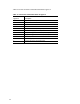
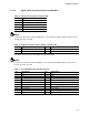
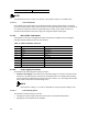
Table 21. USB Type C Connector
Pin
Signal Name
Description
Pin
Signal Name
Description
A12 GND2 Ground B1 GND3 Ground
A11
RX_P2
High speed receive 2 +
B2
TX_P2
High speed transmit 2 +
A10 RX_N2 High speed receive 2 – B3 TX_N2 High speed transmit 2 –
A9
VBUS2
USB bus power
B4
VBUS3
USB bus power
A8 SBU1 Sideband use 1 B5 CC2 Channel config 2
A7
DN1
USB 2.0 data 1 –
B6
DP2
USB 2.0 data 2 +
A6 DP1 USB 2.0 data 1 + B7 DN2 USB 2.0 data 2 –
A5
CC1
Channel config 1
B8
SBU2
Sideband use 2
A4 VBUS1 USB bus power B9 VBUS4 USB bus power
A3
TX_N1
High speed transmit 1 +
B10
RX_N1
High speed receive 1 –
A2 TX_P1 High speed transmit 1 – B11 RX_P1 High speed receive 1 +
A1
GND1
Ground
B12
GND4
Ground
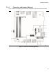
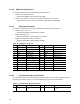
2.2.4.4 Front Panel Header (2.0 mm Pitch)
This section describes the functions of the front panel header. Table 22 lists the signal names of
the front panel header. Figure 13 is a connection diagram for the front panel header.
Table 22. Front Panel Header (2.0 mm Pitch)
Pin
Signal Name
Description
Pin
Signal Name
Description
1 HDD_POWER_LED Pull-up resistor (750 Ω) to
+5V
2 POWER_LED_MAIN [Out] Front panel LED (main
color)