
Specification Sheet


Intel NUC Kit Features
37
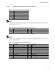
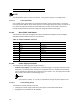
3
HDD_LED#
[Out] Hard disk activity
LED
4
POWER_LED_ALT
[Out] Front panel LED (alt color)
5
GROUND
Ground
6
POWER_SWITCH#
[In] Power switch
7
RESET_SWITCH#
[In] Reset switch
8
GROUND
Ground
9 +5V_DC Power 10 Key No pin
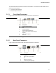
Figure 13. Connection Diagram for Front Panel Header (2.0 mm Pitch)
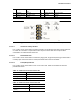
2.2.4.4.1 Hard Drive Activity LED Pins
Pins 1 and 3 can be connected to an LED to provide a visual indicator that data is being read from
or written to a hard drive. Proper LED function requires a SATA hard drive or optical drive
connected to an onboard SATA connector.
2.2.4.4.2 Reset Switch Pins
Pins 5 and 7 can be connected to a momentary single pole, single throw (SPST) type switch that is
normally open. When the switch is closed, the board resets and runs the POST.
2.2.4.4.3 Power/Sleep LED Pins
Pins 2 and 4 can be connected to a one- or two-color LED. Table 23 and Table 24 show the
possible LED states.
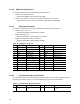
Table 23. States for a One-Color Power LED
LED State
Description
Off
Power off
Blinking
Standby
Steady
Normal operation
Table 24. States for a Dual-Color Power LED
LED State
Description
Off
Power off
Secondary color blinking
(amber)
Standby