
Specification Sheet


38
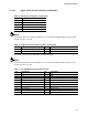
Primary color steady (Blue)
Normal operation
NOTE
The LED behavior shown in Table 23 is default – other patterns may be set via BIOS setup.
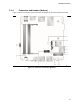
2.2.4.4.4 Power Switch Pins
Pins 6 and 8 can be connected to a front panel momentary-contact power switch. The switch
must pull the SW_ON# pin to ground for at least 50 ms to signal the power supply to switch on or
off. (The time requirement is due to internal debounce circuitry on the board.) At least two
seconds must pass before the power supply will recognize another on/off signal.
2.2.4.5 Micro SDXC Card Reader
The board has a micro Secure Digital (Micro SD) card reader that supports the Secure Digital
eXtended Capacity (SDXC) format, 3.01 specification.
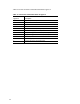
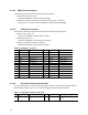
Table 25. SDXC Card Reader Connector
Pin
Signal Name
Descriptive Name
1 CD Card Detection
2
DATA1
Serial Data 1
3
DATA0
Serial Data 0
4
GND
Ground
5 CLK Serial Clock
6
VDD
Power (3.3 V)
7
CMD
Command
8
DATA3
Serial Data 3
9 DATA2 Serial Data 2
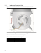
2.2.4.6 Power Supply Connector
The board has the following power supply connector:
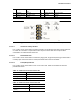
• External Power Supply – the board can be powered through a 12-19 V DC connector on the
back panel. The back panel DC connector is compatible with a 5.5 mm/OD (outer diameter)
and 2.5 mm/ID (inner diameter) plug, where the inner contact is +12-19 (±10%) V DC and the
shell is GND. The maximum current rating is 10 A.
NOTE
External power voltage, 12-19 V DC, is dependent on the type of power adapter used.
2.2.4.6.1 Power Sensing Circuit
The board has a power sensing circuit that:
• Manages CPU power usage to maintain system power consumption below 90 W.
• Designed for use with 90 W AC-DC adapters.