
Datasheet


Pentium
®
III Xeon™ Processor at 500 and 550 MHz
36
Datasheet
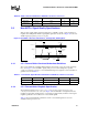
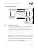
3.3.3 2.5 V Tolerant Buffer Settling Limit Guideline
Settling limit defines the maximum amount of ringing at the receiving pin that a signal must reach
before its next transition. The amount allowed is 10% of the total signal swing (V
HI
– V
LO
) above
and below its final value. A signal should be within the settling limits of its final value, when either
in its high state or low state, before it transitions again.
Violation of the settling limit guideline is acceptable if simulations of 5 to 10 successive transitions
do not show the amplitude of the ringing increasing in the subsequent transitions.
4.0 Processor Feature
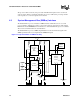
4.1 Functional Redundancy Checking Mode
Two Pentium
III
Xeon processor agents may be configured as an FRC (functional redundanc
checking) pair. In this configuration, one processor acts as the master and the other acts as a
checker, and the pair operates as a single processor. If the checker agent detects a mismatch
between its internally sampled outputs and the master processor’s outputs, the checker asserts
FRCERR. FRCERR observation can be enabled at the master processor with software. The master
enters machine check on an FRCERR provided that Machine Check Execution is enabled.
For proper synchronization of signals when operating in FRC mode, see Section 9.1.23. ITP
operation is not supported in FRC mode.
Systems configured to implement FRC mode must write all of the processors’ internal MSRs to
deterministic values before performing either a read or read-modify-write operation using these
registers. The following is a list of MSRs that are not initialized by the processors’ reset sequences.
1. All fixed and variable MTRRs,
2. All Machine Check Architecture (MCA) status registers,
3. Microcode Update signature register, and
4. All L2 Cache initialization MSRs.
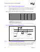
Table 22. Signal Ringback Specifications fo r 2.5V Tolerant Signal Simulation at the
Processor Core
Input Signal Group Transition
Maximum Ringback
(with Input Diodes Present)
Unit Figure
Non-AGTL+ Signals 0
→
11.7V15
Non-AGTL+ Signals 1
→
00.7V15