
Datasheet


Pentium
®
III Xeon™ Processor at 500 and 550 MHz
44
Datasheet
thermal diode is sensed and the precision A/D converter derives a single byte of thermal reference
data, or a “thermal byte reading.” System management software running on the processor or on a
microcontroller can acquire the data from the thermal sensor to thermally manage the system.
Upper and lower thermal reference thresholds can be individually programmed for the thermal
diode. Comparator circuits sample the register where the single byte of thermal data (thermal byte
reading) is stored. These circuits compare the single byte result against programmable threshold
bytes. The alert signal on the Pentium
III
Xeon processor SMBus (SMBALERT#) will assert when
either threshold is crossed.
To increase the usefulness of the thermal diode and thermal sensor, Intel has added a new
procedure to the manufacturing and test flow of the Pentium
III
Xeon processor. This procedure
determines the Thermal Reference Byte and programs it into the Processor Information ROM. The
Thermal Reference Byte is uniquely determined for each unit. The procedure causes each unit to
dissipate its maximum power (which can vary from unit to unit) while at the same time maintaining
the thermal plate at its maximum specified operating temperature. Correctly used, this feature
permits an efficient thermal solution while preserving data integrity.
The thermal byte reading can be used in conjunction with the Thermal Reference Byte in the
Processor Information ROM. Byte 9 of the Processor Information ROM contains the address in the
ROM of this byte, described in more detail in Section 4.3.1. The thermal byte reading from the
thermal sensor can be compared to this Thermal Reference Byte to provide an indication of the
difference between the temperature of the processor core at the instant of the thermal byte reading
and the temperature of the processor core under the steady state conditions of high power and
maximum T
PLATE
specifications. The nominal precision of the least significant bit of a thermal
byte is 1°C.
Reading the thermal sensor is explained in Section 4.3.5. See the
Pentium
®
III
Xeon™ Processor
SMBus Thermal Reference Guidelines
for more details and further recommendations on the use of
this feature in Pentium
III
Xeon processor-based systems.
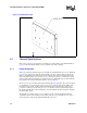
The thermal sensor feature in the processor cannot be used to measure T
PLATE
. The T
PLATE
specification in Section 5.0 must be met regardless of the reading of the processor's thermal sensor
in order to ensure adequate cooling for the entire Pentium
III
Xeon processor. The thermal sensor
feature is only available while V
CC
CORE
and V
CC
SMB
US
are at valid levels and the processor is not
in a low-power state.
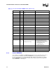
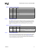
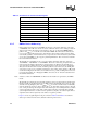
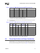
4.3.5 Thermal Sensor Supported SMBus Transactions
The thermal sensor responds to five of the SMBus packet types: write byte, read byte, send byte,
receive byte, and Alert Response Address (ARA). The send byte packet is used for sending one-
shot commands only. The receive byte packet accesses the register commanded by the last read
byte packet. If a receive byte packet was preceded by a write byte or send byte packet more recently
than a read byte packet, then the behavior is undefined. Table 27 through Table 31 diagram the five
packet types. In these figures, ‘S’ represents the SMBus start bit, ‘P’ represents a stop bit, ‘Ack’
represents an acknowledge, and ‘///’ represents a negative acknowledge. The shaded bits are
transmitted by the thermal sensor, and the bits that aren’t shaded are transmitted by the SMBus host
controller. Table 32 shows the encoding of the command byte.