
Datasheet


Pentium
®
III Xeon™ Processor at 500 and 550 MHz
Datasheet
83
8.1.4.1 General Signal Quality Notes
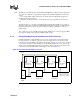
Signals from the debug port are fed to the system from an ITP via a buffer board and a cable. If
system signals routed to the debug port (i.e., TDO, PRDY[x]# and RESET#) are used elsewhere in
the system, then dedicated drivers should be used to isolate the signals from reflections coming
from the end of this cable. If the Pentium
III
Xeon processor boundary scan signals are used
elsewhere in the system, then the TDI, TMS, TCK, and TRST# signals from the debug port should
be isolated from the system signals.
In general, no signals should be left floating. Thus, signals going from the debug port to the
processor system should not be left floating. If they are left floating, there may be problems when
an ITP is not plugged into the connector.
8.1.4.2 Signal Note: DBRESET#
The DBRESET# output signal from an ITP is an open drain with about 5
Ω
of R
DS
. The usual
implementation is to connect it to the PWROK open drain signal on the PCIset components as an
OR input to initiate a system reset. In order for the DBRESET# signal to work properly, it must
actually reset the entire target system. The signal should be pulled up (Intel recommends a 240
Ω
resistor, but system designers will need to fine tune specific system designs) to meet two
considerations: (1) the signal must be able to meet V
IL
of the system, and (2) it must allow the
signal to meet the specified rise time. When asserted by an ITP, the DBRESET# signal will remain
asserted for 100 ms. A large capacitance should not be present on this signal as it may prevent a full
charge from building up within 100 ms.
8.1.4.3 Signal Note: TDO and TDI
The TDO signal of each processor has a 2.5V Tolerant open-drain driver. The TDI signal of each
processor contains a 150
Ω
pull-up to V
CC
TAP
. When connecting one Pentium
III
Xeon processor
to the next, or connecting to the TDI of the first processor, no external pull-up is required. However,
the last processor of the chain does require a pull-up before passing the signal to the next device in
the chain.
8.1.4.4 Signal Note: TCK
Warning:
A significant number of target systems have had signal integrity issues with the TCK signal. TCK
is a critical clock signal and must be routed accordingly; make sure to observe power and ground
plane integrity for this signal. Follow the guidelines below and assure the quality of the signal when
beginning use of an ITP to debug your target.
A significant number of target systems using series terminations methods in MP systems
exhibited signal integrity problems on TCK which prevented the use of the debug port and
inhibited system debugging. In the paragraphs that follow, Intel has since suggested changing to a
simple LC (Bessel) Filter as a strongly suggested improvement to your target design. Bessel
filtering is not necessarily required for existing systems that are already working. This method
should, however, be used in all future debug port designs.
The use of buffering of the individual TCK lines in an MP system is a design requirement.
All the design suggestions and requirements that follow require the individual designer to
determine component values and TCK implementation success with the use of target design
simulations and/or testing.