
Specification Sheet


Intel
®
Xeon
®
Processor E5-1600/E5-2600/E5-4600 v2 Product Families 33
Datasheet Volume One of Two
Interfaces
2.5.1.2 Platform Manageability
PECI allows read access to certain error registers in the processor MSR space and
status monitoring registers in the PCI configuration space within the processor and
downstream devices. Details are covered in subsequent sections.
PECI permits writes to certain Memory Controller RAS-related registers in the processor
PCI configuration space. Details are covered in Section 2.5.2.10.
2.5.2 Client Command Suite
PECI command requires at least one frame check sequence (FCS) byte to ensure
reliable data exchange between originator and client. The PECI message protocol
defines two FCS bytes that are returned by the client to the message originator. The
first FCS byte covers the client address byte, the Read and Write Length bytes, and all
bytes in the write data block. The second FCS byte covers the read response data
returned by the PECI client. The FCS byte is the result of a cyclic redundancy check
(CRC) of each data block.
2.5.2.1 Ping()
Ping() is a required message for all PECI devices. This message is used to enumerate
devices or determine if a device has been removed, been powered-off, and so forth. A
Ping() sent to a device address always returns a non-zero Write FCS if the device at the
targeted address is able to respond.
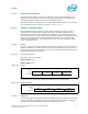
2.5.2.1.1 Command Format
The Ping() format is as follows:
Wr
ite Length: 0x00
Read Length: 0x00
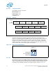
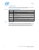
An example Ping() command to PECI device address 0x30 is shown below.
2.5.2.2 GetDIB()
The processor PECI client implementation of GetDIB() includes an 8-byte response and
provides information regarding client revision number and the number of supported
domains. All processor PECI clients support the GetDIB() command.
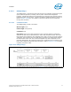
Figure 2-3. Ping()
Byte #
Byte
Definition
0
Client Address
1
Write Length
0x00
2
Read Length
0x00
3
FCS
Figure 2-4. Ping() Example
Byte #
Byte
Definition
0
0x30
1
0x00
2
0x00
3
0xe1