User Guide for NUC10i7FNHN, NUC10i5FNHN, NUC10i3FNHN Intel® NUC Kit NUC10i7FNHN Intel® NUC Kit NUC10i5FNHN Intel® NUC Kit NUC10i3FNHN User Guide 1
User Guide for NUC10i7FNHN, NUC10i5FNHN, NUC10i3FNHN Before You Begin CAUTIONS The steps in this guide assume you’re familiar with computer terminology and with the safety practices and regulatory compliance required for using and modifying computer equipment. Disconnect the computer from its power source and from any network before performing any of the steps described in this guide.
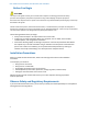
User Guide for NUC10i7FNHN, NUC10i5FNHN, NUC10i3FNHN This guide tells you how to: Install and remove memory Install an M.2 SSD Install a 2.5” drive Install a VESA mount bracket Connect power Install an operating system Install the latest drivers • • • • • • • Open the Chassis To open the Intel NUC chassis, follow these steps: 1. Unscrew the four corner screws on the bottom cover of the chassis and lift the cover.
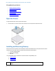
User Guide for NUC10i7FNHN, NUC10i5FNHN, NUC10i3FNHN To install memory, follow these steps: 1. 2. Observe the precautions in "Before You Begin" on page 2. Turn off all peripheral devices connected to the computer. Turn off the computer and disconnect the power cord. Remove the computer’s bottom chassis cover. 3. 4. 5. 6. Align the small space at the bottom edge of the memory module with the key in the socket. Insert the bottom edge of the module at a 45-degree angle into the socket (A).
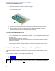
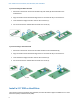
User Guide for NUC10i7FNHN, NUC10i5FNHN, NUC10i3FNHN If you’re installing an 80mm M.2 SSD: 1. Remove the small silver screw from the 80mm (A) and 42mm (B) metal standoff on the motherboard. 2. Align the small notch at the bottom edge of the M.2 card with the key in the connector. 3. Insert the bottom edge of the M.2 card into the connector (C). 4. Secure the card to the standoff with the small silver screw (D). If you’re installing a 42mm M.2 SSD: 1.
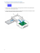
User Guide for NUC10i7FNHN, NUC10i5FNHN, NUC10i3FNHN Find compatible 2.5” drives in the Intel Product Compatibility Tool: NUC10i7FNHN NUC10i5FNHN NUC10i3FNHN 1. Slide the new 2.5” drive into the drive bay, ensuring the SATA connectors are fully seated into the connectors of the SATA daughter card (A). 2. Secure the drive into the drive bay with the two smallest black screws that were included in the box (B). Set the drive bay bracket down inside the chassis (C).
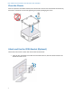
User Guide for NUC10i7FNHN, NUC10i5FNHN, NUC10i3FNHN Close the Chassis After all components have been installed, close the Intel NUC chassis. Intel recommends this be done by hand with a screwdriver to avoid over-tightening and possibly damaging the screws. Attach and Use the VESA Bracket (Optional) Follow these instructions to attach and use the VESA mount bracket: 1. 7 Using the four small black screws that were included in the box, attach the VESA bracket to the back of the monitor or TV.
User Guide for NUC10i7FNHN, NUC10i5FNHN, NUC10i3FNHN 2. Attach the two slightly larger black screws to the bottom chassis cover of the Intel NUC. 3. 8 Slide the Intel NUC onto the VESA mount bracket.
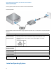
User Guide for NUC10i7FNHN, NUC10i5FNHN, NUC10i3FNHN Connect Power Country-specific power cords are included in the Intel NUC Kit box. Connect AC power Each Intel NUC model includes either a region-specific AC power cord or no AC power cord (only the power adapter). Product codes BXNUC10i7FNHN, BXNUC10i5FNHN, BXNUC10i3FNHN Power cord type No power cord included. An AC power cord needs to be purchased separately. Power cords are available at many Internet sites for use in multiple countries.
User Guide for NUC10i7FNHN, NUC10i5FNHN, NUC10i3FNHN Refer to Supported Operating Systems for a list of Intel-validated Windows* operating systems and versions of Linux that have been reported as compatible by Intel NUC owners. Refer to Operating System Installation for system requirements and installation steps.