
Datasheet


Processor Configuration Registers
Intel
®
Core
TM
i7-660UE, i7-620LE/UE, i7-610E, i5-520E, i3-330E and Intel
®
Celeron
®
Processor P4505, U3405 Series
Datasheet Addendum August 2010
112 Document Number: 323178-003
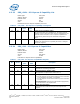
6.2.33 PEG_CAPL - PCI Express-G Capability List
B/D/F/Type: 0/6/0/PCI
Address Offset: A0-A1h
Default Value: 0010h
Access: RO
Size: 16 bits
Enumerates the PCI Express capability structure.
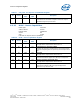
6.2.34 PEG_CAP - PCI Express-G Capabilities
B/D/F/Type: 0/6/0/PCI
Address Offset: A2-A3h
Default Value: 0142h
Access: RO; RW-O
Size: 16 bits
Indicates PCI Express device capabilities.
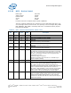
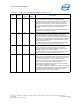
Table 56. PEG_CAPL - PCI Express-G Capability List Register
Bit Access
Default
Value
RST/
PWR
Description
15:8 RO 00h Core Pointer to Next Capability (PNC)
This value terminates the capabilities list. The Virtual Channel
capability and any other PCI Express specific capabilities that are
reported via this mechanism are in a separate capabilities list
located entirely within PCI Express Extended Configuration
Space.
7:0 RO 10h Core Capability ID (CID)
Identifies this linked list item (capability structure) as being for
PCI Express registers.
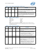
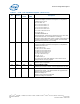
Table 57. PEG_CAP - PCI Express-G Capabilities Register
Bit Access
Default
Value
RST/
PWR
Description
15 RO 0b Core Reserved
14 RO 0b Core Reserved
Reserved for TCS Routing Supported.
13:9 RO 00h Core Interrupt Message Number (IMN)
Not Applicable or Implemented. Hard wired to 0.
8RW-O 1b CoreSlot Implemented (SI)
0 = The PCI Express Link associated with this port is connected
to an integrated component or is disabled.
1 = The PCI Express Link associated with this port is connected
to a slot.
BIOS Requirement: This field must be initialized appropriately
if a slot connection is not implemented.
7:4 RO 4h Core Device/Port Type (DPT)
hard wired to 4h to indicate root port of PCI Express Root
Complex.