
Datasheet


Intel
®
Core
TM
i7-660UE, i7-620LE/UE, i7-610E, i5-520E, i3-330E and Intel
®
Celeron
®
Processor P4505, U3405 Series
August 2010 Datasheet Addendum
Document Number: 323178-003 117
Processor Configuration Registers
21 RO 1b Core Link Bandwidth Notification Capability (LBNC)
A value of 1b indicates support for the Link Bandwidth
Notification status and interrupt mechanisms. This capability is
required for all Root Ports and Switch downstream ports
supporting Links wider than x1 and/or multiple Link speeds.
This field is not applicable and is reserved for Endpoint devices,
PCI Express to PCI/PCI-X bridges, and Upstream Ports of
Switches.
Devices that do not implement the Link Bandwidth Notification
capability must hardwire this bit to 0b.
20 RO 0b Core Data Link Layer Link Active Reporting Capable (DLLLARC)
For a Downstream Port, this bit must be set to 1b if the
component supports the optional capability of reporting the
DL_Active state of the Data Link Control and Management State
Machine. For a hot-plug capable Downstream Port (as indicated
by the Hot-Plug Capable field of the Slot Capabilities register),
this bit must be set to 1b.
For Upstream Ports and components that do not support this
optional capability, this bit must be hard wired to 0b.
19 RO 0b Core Surprise Down Error Reporting Capable (SDERC)
For a Downstream Port, this bit must be set to 1b if the
component supports the optional capability of detecting and
reporting a Surprise Down error condition.
For Upstream Ports and components that do not support this
optional capability, this bit must be hard wired to 0b.
18 RO 0b Core Clock Power Management (CPM)
A value of 1b in this bit indicates that the component tolerates
the removal of any reference clock(s) when the link is in the L1
and L2/3 Ready link states. A value of 0b indicates the
component does not have this capability and that reference
clock(s) must not be removed in these link states.
This capability is applicable only in form factors that support
“clock request” (CLKREQ#) capability.
For a multi-function device, each function indicates its capability
independently. Power Management configuration software must
only permit reference clock removal if all functions of the
multifunction device indicate a 1b in this bit.
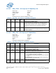
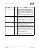
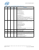
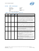
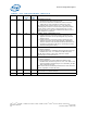
Table 61. LCAP - Link Capabilities Register (Sheet 2 of 3)
Bit Access
Default
Value
RST/
PWR
Description