
Datasheet


Processor Configuration Registers
Intel
®
Core
TM
i7-660UE, i7-620LE/UE, i7-610E, i5-520E, i3-330E and Intel
®
Celeron
®
Processor P4505, U3405 Series
Datasheet Addendum August 2010
120 Document Number: 323178-003
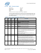
7RW 0bCoreExtended Synch (ES)
0 = Standard Fast Training Sequence (FTS).
1 = Forces the transmission of additional ordered sets when
exiting the L0s state and when in the Recovery state.
This mode provides external devices (e.g., logic analyzers)
monitoring the Link time to achieve bit and symbol lock before
the link enters L0 and resumes communication.This is a test
mode only and may cause other undesired side effects such as
buffer overflows or underruns.
6RW 0bCoreCommon Clock Configuration (CCC)
0 = Indicates that this component and the component at the
opposite end of this Link are operating with asynchronous
reference clock.
1 = Indicates that this component and the component at the
opposite end of this Link are operating with a distributed
common reference clock.The state of this bit affects the L0s
Exit Latency reported in LCAP[14:12] and the N_FTS value
advertised during link training.
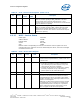
5RW-SC 0b CoreRetrain Link (RL)
0 = Normal operation.
1 = Full Link retraining is initiated by directing the Physical Layer
LTSSM from L0, L0s, or L1 states to the Recovery state.
This bit always returns 0 when read. This bit is cleared
automatically (no need to write a 0).
4RW 0bCoreLink Disable (LD)
0 = Normal operation
1 = Link is disabled. Forces the LTSSM to transition to the
Disabled state (via Recovery) from L0, L0s, or L1 states. Link
retraining happens automatically on 0 to 1 transition, just like
when coming out of reset.
Writes to this bit are immediately reflected in the value read from
the bit, regardless of actual Link state.
3RO 0bCoreRead Completion Boundary (RCB)
hard wired to 0 to indicate 64 byte.
2RO 0bCoreReserved (FEDLB)
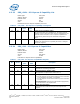
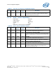
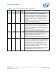
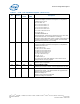
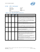
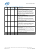
Table 62. LCTL - Link Control Register (Sheet 2 of 3)
Bit Access Default
Value
RST/
PWR
Description