
Datasheet


Processor Configuration Registers
Intel
®
Core
TM
i7-660UE, i7-620LE/UE, i7-610E, i5-520E, i3-330E and Intel
®
Celeron
®
Processor P4505, U3405 Series
Datasheet Addendum August 2010
130 Document Number: 323178-003
6.2.45 RSTS - Root Status
B/D/F/Type: 0/6/0/PCI
Address Offset: C0-C3h
Default Value: 00000000h
Access: RO; RWC
Size: 32 bits
Provides information about PCI Express Root Complex specific parameters.
6.2.46 LCTL2 - Link Control 2
B/D/F/Type: 0/6/0/PCI
Address Offset: D0-D1h
Default Value: 0001h
Access: RO; RW-S; RW;
Size: 16 bits
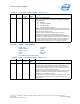
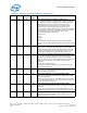
Table 68. RSTS - Root Status Register
Bit Access
Default
Value
RST/
PWR
Description
31:18 RO 0000h Core Reserved and Zero (RSVD)
For future R/WC/S implementations; software must use 0 for
writes to bits.
17 RO 0b Core PME Pending (PMEP)
Indicates that another PME is pending when the PME Status bit
is set. When the PME Status bit is cleared by software; the PME
is delivered by hardware by setting the PME Status bit again
and updating the Requestor ID appropriately. The PME pending
bit is cleared by hardware if no more PMEs are pending.
16 RWC 0b Core PME Status (PMES)
Indicates that PME was asserted by the requestor ID indicated
in the PME Requestor ID field. Subsequent PMEs are kept
pending until the status register is cleared by writing a 1 to this
field.
15:0 RO 0000h Core PME Requestor ID (PMERID)
Indicates the PCI requestor ID of the last PME requestor.
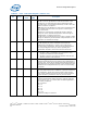
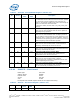
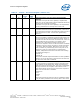
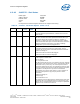
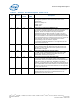
Table 69. LCTL2 - Link Control 2 Register (Sheet 1 of 3)
Bit Access Default
Value
RST/
PWR
Description
15:13 RO 000b Core Reserved (RSVD):