
Datasheet


Interfaces
Intel
®
Core
TM
i7-660UE, i7-620LE/UE, i7-610E, i5-520E, i3-330E and Intel
®
Celeron
®
Processor P4505, U3405 Series
Datasheet Addendum August 2010
16 Document Number: 323178-003
2.1.2 System Memory Timing Support
The IMC supports the following DDR3 Speed Bin, CAS Write Latency (CWL), and
command signal mode timings on the main memory interface:
• tCL = CAS Latency
• tRCD = Activate Command to READ or WRITE Command delay
• tRP = PRECHARGE Command Period
• CWL = CAS Write Latency
• Command Signal modes = 1n indicates a new command may be issued every
clock. Command launch mode programming depends on the transfer rate and
memory configuration.
2.1.3 System Memory Organization Modes
The IMC supports two memory organization modes, single-channel and dual-channel.
Depending upon how the DIMM Modules are populated in each memory channel, a
number of different configurations can exist.
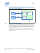
2.1.3.1 Single-Channel Mode
In this mode, all memory cycles are directed to a single-channel. Single-channel mode
is used when either Channel A or Channel B DIMM connectors are populated in any
order, but not both.
D
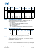
512 MB 512 Mb 64 M x 8 9 1 13/10 8 8K
1 GB 1 Gb 128 M x 8 9 1 14/10 8 8K
2 GB 2 Gb 256 M x 8 9 1 15/10 8 8K
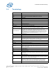
E
1 GB 512 Mb 64M x 8 18 2 13/10 8 8K
2 GB 1 Gb 128 M x 8 18 2 14/10 8 8K
4 GB 2 Gb 256 M x 8 18 2 15/10 8 8K
F
512 MB 512 Mb 32 M x 16 8 2 12/10 8 8K
1 GB 1 Gb 64 M x 16 8 2 13/10 8 8K
2 GB 2 Gb 128 M x 16 8 2 14/10 8 8K
Table 4. Supported DIMM Module Configurations (Sheet 2 of 2)
Raw
Card
Version
DIMM
Capacity
DRAM
Device
Technology
DRAM
Organization
# of
DRAM
Devices
# of
Physical
Device
Ranks
# of Row/
Col
Address
Bits
# of
Banks
Inside
DRAM
Page
Size
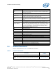
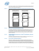
Table 5. DDR3 System Memory Timing Support
Transfer
Rate
(MT/s)
tCL
(tCK)
tRCD
(tCK)
tRP
(tCK)
CWL
(tCK)
CMD Mode Notes
800 6 6 6 5 1n 1
1066
777
61n 1
888
NOTES:
1. System Memory timing support is based on availability and is subject to change.