
Datasheet

Signal Description
Intel
®
Core
TM
i7-660UE, i7-620LE/UE, i7-610E, i5-520E, i3-330E and Intel
®
Celeron
®
Processor P4505, U3405 Series
Datasheet Addendum August 2010
24 Document Number: 323178-003
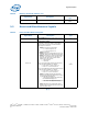
3.2 Reset and Miscellaneous Signals
§ §
SB_ODT[1:0] On Die Termination: Active Termination Control.
O
DDR3
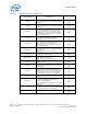
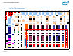
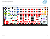
Table 9. Reset and Miscellaneous Signals
Signal Name Description
Direction/Buffer
Type
SM_DRAMRST#
DDR3 DRAM Reset: Reset signal from processor
to DRAM devices. One for all channels of DIMMs.
O
DDR3
CFG[17:0]
Configuration signals:
The CFG signals have a default value of 1 if not
terminated on the board. Refer to the Platform
Design Guide for pull-down recommendations
when logic low is desired.
• CFG[0]: PCI Express* Bifurcation:
— 1 = 1 x16 PCI Express I/O
— 0 = 2 x 8 PCI Express I/O
• CFG[1]: Reserved
• CFG[2]: Reserved configuration lands. A test
point may be placed on the board for this land.
• CFG[3]: PCI Express* Static Lane Numbering
Reversal. A test point may be placed on the
board for this land. Lane reversal will be
applied across all 16 lanes.
—1: No Reversal
—0: Reversal
In the case of Bifurcation with NO Lane Reversal
the physical lane mapping is as follows:
— Lanes 15:8 => Port 1 Lanes 7:0
— Lanes 7:0 => Port 0 Lanes 7:0
In the case of Bifurcation with WITH Lane Reversal
the physical lane mapping is as follows:
— Lanes 15:8 => Port 0 Lanes 0:7
— Lanes 7:0 => Port 1 Lanes 0:7
• CFG[4]: Embedded DisplayPort Detection:
This is used to detect the presence of a device
on the Embedded DisplayPort.
— 1: No Physical Display Port attached to
the Embedded Display Port
— 0: An external Display Port device is
connected to the Embedded Display Port
• CFG[17:5]: Reserved configuration lands.
Intel does not recommend a test point on the
board for these lands.
I
CMOS
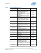
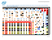
Table 8. Memory Channel B (Sheet 2 of 2)
Signal Name Description
Direction/Buffer
Type