
Intel Celeron D Processor 300 Sequence
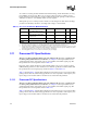
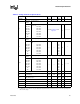
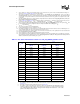
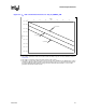
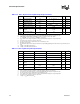
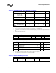
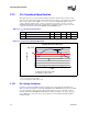
Table Of Contents
- Contents
- Revision History
- 1 Introduction
- 2 Electrical Specifications
- 2.1 FSB and GTLREF
- 2.2 Power and Ground Lands
- 2.3 Decoupling Guidelines
- 2.4 Voltage Identification
- 2.5 Reserved, Unused, and TESTHI Signals
- 2.6 FSB Signal Groups
- 2.7 GTL+ Asynchronous Signals
- 2.8 Test Access Port (TAP) Connection
- 2.9 FSB Frequency Select Signals (BSEL[2:0])
- 2.10 Absolute Maximum and Minimum Ratings
- 2.11 Processor DC Specifications
- 2.12 VCC Overshoot Specification
- 2.13 GTL+ FSB Specifications
- 3 Package Mechanical Specifications
- 4 Land Listing and Signal Descriptions
- 5 Thermal Specifications and Design Considerations
- 6 Features
- 7 Boxed Processor Specifications
- 8 Debug Tools Specifications
Datasheet 25
Electrical Specifications
Table 2-8. Voltage and Current Specifications
Symbol Parameter Min Typ Max Unit Notes
VID range VID 1.250 — 1.400 V
1
NOTES:
1. Individual processor VID values may be calibrated during manufacturing such that two devices at the same speed may have
different VID settings.
V
CC
Processor
Number
Core Frequency
325J/326
330J/331
335J/336
340J/341
345J/346
351
355
V
CC
for 775_VR_CONFIG_04A
processors
2.53 GHz
2.66 GHz
2.80 GHz
2.93 GHz
3.06 GHz
3.20 GHz
3.33 GHz
Refer to Table 2-9 and
Figure 2-2
V
2, 3,
4, 5, 6
I
CC
Processor
Number
Core Frequency
325J/326
330J/331
335J/336
340J/341
345J/346
351
355
I
CC
for processor with multiple
VID
2.53 GHz
2.66 GHz
2.80 GHz
2.93 GHz
3.06 GHz
3.20 GHz
3.33 GHz
——
78
78
78
78
78
78
78
A
7
I
SGNT
Processor
Number
Core Frequency
325J/326
330J/331
335J/336
340J/341
345J/346
351
355
I
CC
Stop-Grant
2.53 GHz
2.66 GHz
2.80 GHz
2.93 GHz
3.06 GHz
3.20 GHz
3.33 GHz
——
40
40
40
40
40
40
40
A
8, 9, 13
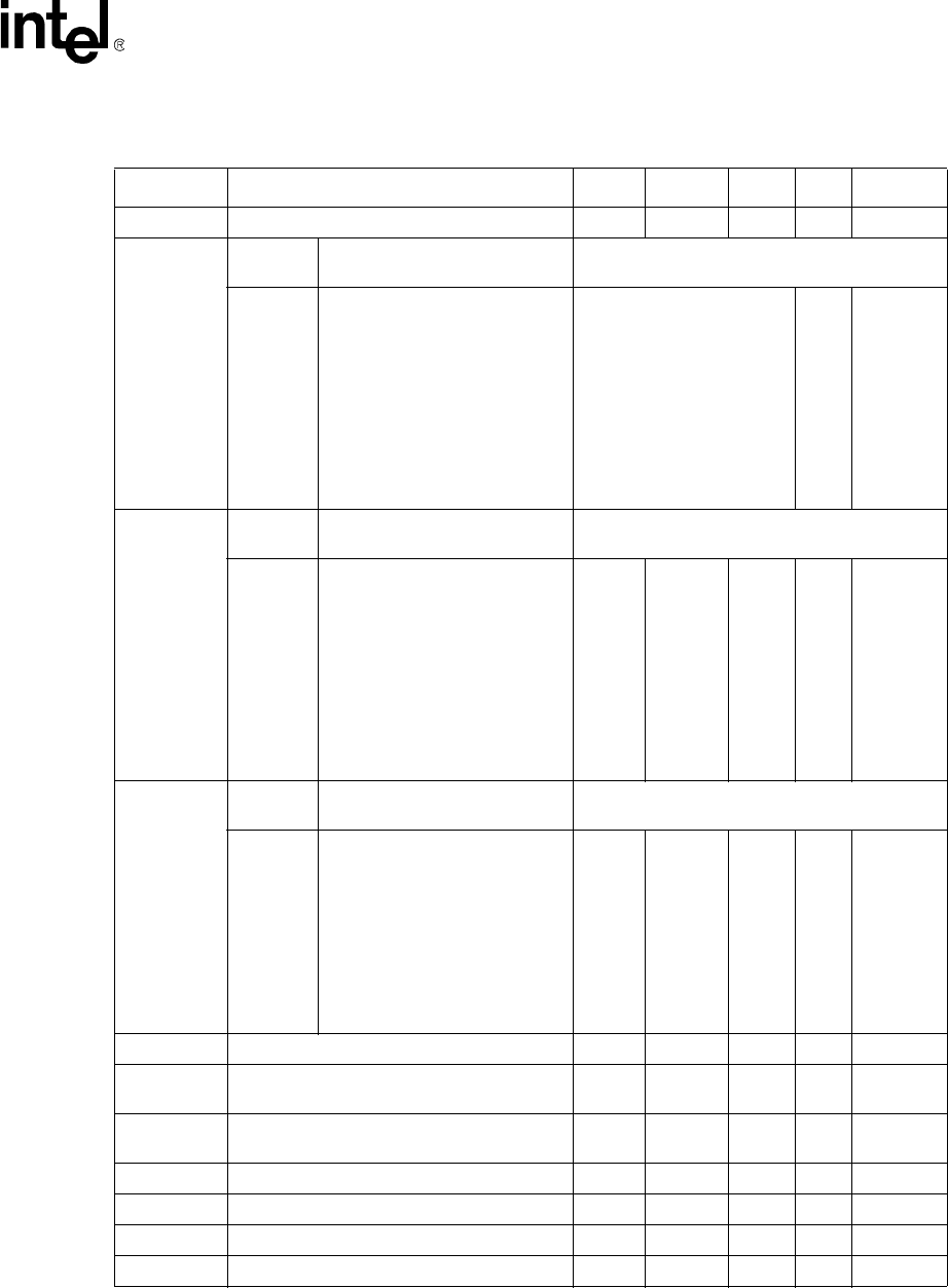
I
TCC
I
CC
TCC active — — I
CC
A
10
V
TT
FSB termination voltage (DC+AC
specifications)
1.14 1.20 1.26 V
11, 12
VTT_OUT
I
CC
DC Current that may be drawn from
VTT_OUT per pin
— — 580 mA —
I
TT
FSB termination current — — 3.5 A
13, 14
I
CC_VCCA
I
CC
for PLL lands — — 120 mA
13
I
CC_VCCIOPLL
I
CC
for I/O PLL land — — 100 mA
13
I
CC_GTLREF
I
CC
for GTLREF — — 200 μA
13