
Intel Celeron D Processor 300 Sequence
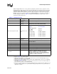
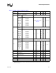
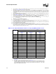
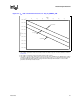
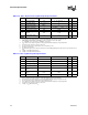
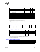
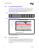
Table Of Contents
- Contents
- Revision History
- 1 Introduction
- 2 Electrical Specifications
- 2.1 FSB and GTLREF
- 2.2 Power and Ground Lands
- 2.3 Decoupling Guidelines
- 2.4 Voltage Identification
- 2.5 Reserved, Unused, and TESTHI Signals
- 2.6 FSB Signal Groups
- 2.7 GTL+ Asynchronous Signals
- 2.8 Test Access Port (TAP) Connection
- 2.9 FSB Frequency Select Signals (BSEL[2:0])
- 2.10 Absolute Maximum and Minimum Ratings
- 2.11 Processor DC Specifications
- 2.12 VCC Overshoot Specification
- 2.13 GTL+ FSB Specifications
- 3 Package Mechanical Specifications
- 4 Land Listing and Signal Descriptions
- 5 Thermal Specifications and Design Considerations
- 6 Features
- 7 Boxed Processor Specifications
- 8 Debug Tools Specifications
26 Datasheet
Electrical Specifications
2. These voltages are targets only. A variable voltage source should exist on systems in the event that a different voltage is re-
quired. See Section 2.4 and Table 2-2 for more information.
3. The voltage specification requirements are measured across VCC_SENSE and VSS_SENSE lands at the socket with a
100 MHz bandwidth oscilloscope, 1.5 pF maximum probe capacitance, and 1 MΩ minimum impedance. The maximum length
of ground wire on the probe should be less than 5 mm. Ensure external noise from the system is not coupled into the oscillo-
scope probe.
4. 775_VR_CONFIG_04A refers to voltage regulator configurations that are defined in the Voltage Regulator Down (VRD) 10.1
Design Guide For Desktop LGA775 Socket.
5. Refer to Table 2-9 and Figure 2-2 for the minimum, typical, and maximum V
CC
allowed for a given current. The processor
should not be subjected to any V
CC
and I
CC
combination wherein V
CC
exceeds V
CC_max
for a given current.
6. These frequencies will operate properly in a system designed for 775_VR_CONFIG_04B processors. The power and I
CC
will
be incrementally higher in this configuration due to the improved loadline and resulting higher V
CC
.
7. I
CC_max
is specified at V
CC_max
.
8. The current specified is also for AutoHALT State.
9. Icc Stop-Grant and I
CC
Sleep are specified at V
CC_max
.
10. The maximum instantaneous current the processor will draw while the thermal control circuit is active as indicated by the as-
sertion of PROCHOT# is the same as the maximum Icc for the processor.
11. VTT must be provided via a separate voltage source and not be connected to V
CC
. This specification is measured at the land.
12. Baseboard bandwidth is limited to 20 MHz.
13. These parameters are based on design characterization and are not tested.
14. This is maximum total current drawn from V
TT
plane by only the processor. This specification does not include the current com-
ing from R
TT
(through the signal line). Refer to the Voltage Regulator Down (VRD) 10.1 Design Guide For Desktop LGA775
Socket to determine the total I
TT
drawn by the system.
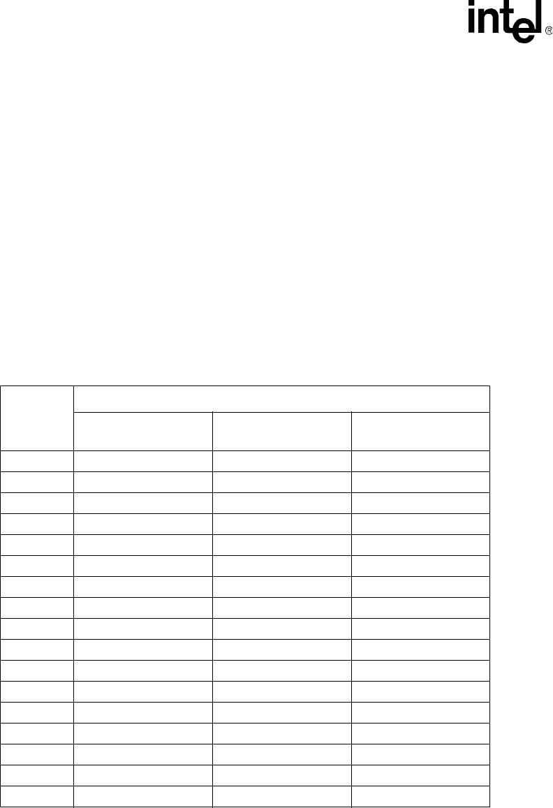
Table 2-9. V
CC
Static and Transient Tolerance for 775_VR_CONFIG_04A Processors
I
CC
(A)
Voltage Deviation from VID Setting (V)
1, 2, 3
NOTES:
1. The loadline specification includes both static and transient limits except for overshoot allowed as shown in
Section 2.12.
2. This table is intended to aid in reading discrete points on Figure 2-2.
3. The loadlines specify voltage limits at the die measured at the VCC_SENSE and VSS_SENSE lands. Voltage
regulation feedback for voltage regulator circuits must be taken from processor VCC and VSS lands. Refer
to the Voltage Regulator Down (VRD) 10.1 Design Guide For Desktop LGA775 Socket for socket loadline
guidelines and VR implementation details.
Maximum Voltage
1.70 mΩ
Typical Voltage
1.75 mΩ
Minimum Voltage
1.80 mΩ
0 0.000 -0.025 -0.050
5 -0.009 -0.034 -0.059
10 -0.017 -0.043 -0.068
15 -0.026 -0.051 -0.077
20 -0.034 -0.060 -0.086
25 -0.043 -0.069 -0.095
30 -0.051 -0.078 -0.104
35 -0.060 -0.086 -0.113
40 -0.068 -0.095 -0.122
45 -0.077 -0.104 -0.131
50 -0.085 -0.113 -0.140
55 -0.094 -0.121 -0.149
60 -0.102 -0.130 -0.158
65 -0.111 -0.139 -0.167
70 -0.119 -0.148 -0.176
75 -0.128 -0.156 -0.185
78 -0.133 -0.162 -0.190