
Intel Celeron D Processor 300 Sequence

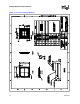
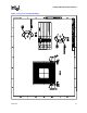
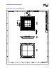
Table Of Contents
- Contents
- Revision History
- 1 Introduction
- 2 Electrical Specifications
- 2.1 FSB and GTLREF
- 2.2 Power and Ground Lands
- 2.3 Decoupling Guidelines
- 2.4 Voltage Identification
- 2.5 Reserved, Unused, and TESTHI Signals
- 2.6 FSB Signal Groups
- 2.7 GTL+ Asynchronous Signals
- 2.8 Test Access Port (TAP) Connection
- 2.9 FSB Frequency Select Signals (BSEL[2:0])
- 2.10 Absolute Maximum and Minimum Ratings
- 2.11 Processor DC Specifications
- 2.12 VCC Overshoot Specification
- 2.13 GTL+ FSB Specifications
- 3 Package Mechanical Specifications
- 4 Land Listing and Signal Descriptions
- 5 Thermal Specifications and Design Considerations
- 6 Features
- 7 Boxed Processor Specifications
- 8 Debug Tools Specifications
Datasheet 33
Package Mechanical Specifications
3 Package Mechanical
Specifications
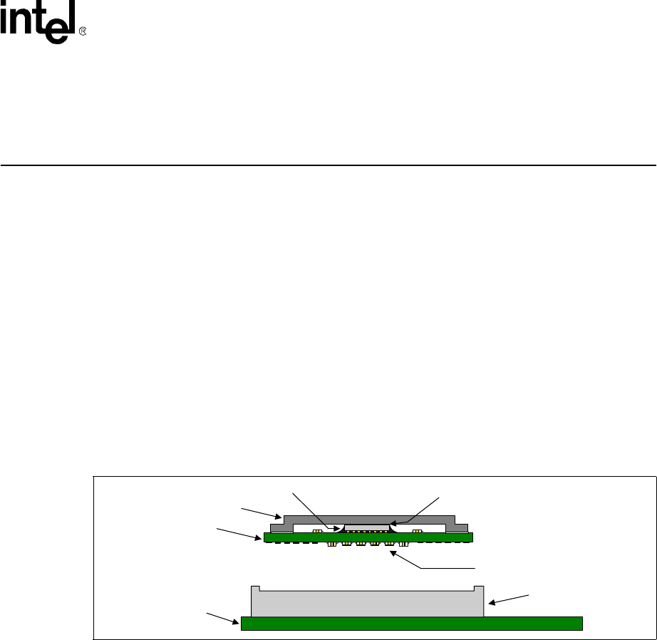
The Celeron D processor in the 775-land package is packaged in a Flip-Chip Land Grid Array
(FC-LGA4) package that interfaces with the motherboard via an LGA775 socket. The package
consists of a processor core mounted on a substrate land-carrier. An integrated heat spreader (IHS)
is attached to the package substrate and core and serves as the mating surface for processor
component thermal solutions, such as a heatsink. Figure 3-1 shows a sketch of the processor
package components and how they are assembled together. Refer to the LGA775 Socket
Mechanical Design Guide for complete details on the LGA775 socket.
The package components shown in Figure 3-1 include the following:
• Integrated Heat Spreader (IHS)
• Thermal Interface Material (TIM)
• Processor core (die)
• Package substrate
• Capacitors
NOTE:
1. Socket and motherboard are included for reference and are not part of processor package.
3.1 Package Mechanical Drawing
The package mechanical drawings are shown in Figure 3-2 through Figure 3-4. The drawings
include dimensions necessary to design a thermal solution for the processor. These dimensions
include:
• Package reference with tolerances (total height, length, width, etc.)
• IHS parallelism and tilt
• Land dimensions
• Top-side and back-side component keep-out dimensions
• Reference datums
All drawing dimensions are in mm [in].
Figure 3-1. Processor Package Assembly Sketch
System Board
LGA775 Socket
Capacitors
TIM
Core (die)
IHS
Substrate