
Intel Celeron D Processor 300 Sequence
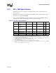

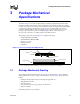
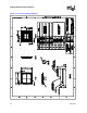
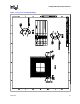
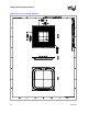
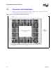
Table Of Contents
- Contents
- Revision History
- 1 Introduction
- 2 Electrical Specifications
- 2.1 FSB and GTLREF
- 2.2 Power and Ground Lands
- 2.3 Decoupling Guidelines
- 2.4 Voltage Identification
- 2.5 Reserved, Unused, and TESTHI Signals
- 2.6 FSB Signal Groups
- 2.7 GTL+ Asynchronous Signals
- 2.8 Test Access Port (TAP) Connection
- 2.9 FSB Frequency Select Signals (BSEL[2:0])
- 2.10 Absolute Maximum and Minimum Ratings
- 2.11 Processor DC Specifications
- 2.12 VCC Overshoot Specification
- 2.13 GTL+ FSB Specifications
- 3 Package Mechanical Specifications
- 4 Land Listing and Signal Descriptions
- 5 Thermal Specifications and Design Considerations
- 6 Features
- 7 Boxed Processor Specifications
- 8 Debug Tools Specifications
Datasheet 37
Package Mechanical Specifications
3.2 Processor Component Keep-Out Zones
The processor may contain components on the substrate that define component keep-out zone
requirements. A thermal and mechanical solution design must not intrude into the required keep-
out zones. Decoupling capacitors are typically mounted to either the topside or land-side of the
package substrate. See Figure 3-2 and Figure 3-3 for keep-out zones.
The location and quantity of package capacitors may change due to manufacturing efficiencies but
will remain within the component keep-in.
3.3 Package Loading Specifications
Table 3-1 provides dynamic and static load specifications for the processor package. These
mechanical maximum load limits should not be exceeded during heatsink assembly, shipping
conditions, or standard use condition. Also, any mechanical system or component testing should
not exceed the maximum limits. The processor package substrate should not be used as a
mechanical reference or load-bearing surface for thermal and mechanical solution. The minimum
loading specification must be maintained by any thermal and mechanical solutions.
.
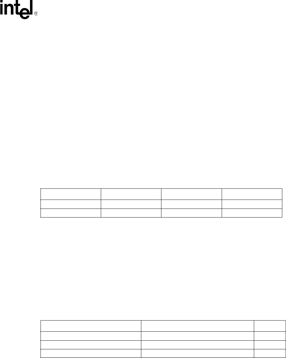
3.4 Package Handling Guidelines
Table 3-2 includes a list of guidelines on package handling in terms of recommended maximum
loading on the processor IHS relative to a fixed substrate. These package handling loads may be
experienced during heatsink removal.
Table 3-1. Processor Loading Specifications
Parameter Minimum Maximum Notes
Static 20 lbf 45 lbf
1, 2, 3
NOTES:
1. These specifications apply to uniform compressive loading in a direction normal to the processor IHS.
2. This is the maximum force that can be applied by a heatsink retention clip. The clip must also provide the minimum spec-
ified load on the processor package.
3. These specifications are based on limited testing for design characterization. Loading limits are for the package only and
do not include the limits of the processor socket.
Dynamic — 145 lbf
1, 3, 4
4. Dynamic loading is defined as an 11 ms duration average load superimposed on the static load requirement.
Table 3-2. Package Handling Guidelines
Parameter Maximum Recommended Notes
Shear 70 lbf
1, 4
NOTES:
1. A shear load is defined as a load applied to the IHS in a direction parallel to the IHS top surface.
Tensile 25 lbf
2, 4
2. A tensile load is defined as a pulling load applied to the IHS in a direction normal to the IHS surface.
Torque 35 lbf-in
3, 4
3. A torque load is defined as a twisting load applied to the IHS in an axis of rotation normal to the IHS top surface.
4. These guidelines are based on limited testing for design characterization.