
Intel Celeron D Processor 300 Sequence
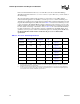
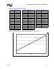
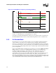
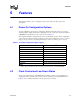
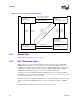
Table Of Contents
- Contents
- Revision History
- 1 Introduction
- 2 Electrical Specifications
- 2.1 FSB and GTLREF
- 2.2 Power and Ground Lands
- 2.3 Decoupling Guidelines
- 2.4 Voltage Identification
- 2.5 Reserved, Unused, and TESTHI Signals
- 2.6 FSB Signal Groups
- 2.7 GTL+ Asynchronous Signals
- 2.8 Test Access Port (TAP) Connection
- 2.9 FSB Frequency Select Signals (BSEL[2:0])
- 2.10 Absolute Maximum and Minimum Ratings
- 2.11 Processor DC Specifications
- 2.12 VCC Overshoot Specification
- 2.13 GTL+ FSB Specifications
- 3 Package Mechanical Specifications
- 4 Land Listing and Signal Descriptions
- 5 Thermal Specifications and Design Considerations
- 6 Features
- 7 Boxed Processor Specifications
- 8 Debug Tools Specifications

72 Datasheet
Thermal Specifications and Design Considerations
Refer to the Intel
®
Pentium
®
4 Processor on 90 nm Process in the 775-Land LGA Package
Thermal Design Guide and the Processor Power Characterization Methodology for the details of
this methodology.
The case temperature is defined at the geometric top center of the processor IHS. Analysis
indicates that real applications are unlikely to cause the processor to consume maximum power
dissipation for sustained periods of time. Intel recommends that complete thermal solution designs
target the Thermal Design Power (TDP) indicated in Table 5-1 instead of the maximum processor
power consumption. The Thermal Monitor feature is intended to help protect the processor in the
unlikely event that an application exceeds the TDP recommendation for a sustained period of time.
For more details on the usage of this feature, refer to Section 5.2. To ensure maximum flexibility
for future requirements, systems should be designed to the Platform Compatibility Guide ‘04 A
guidelines, even if a processor with a lower thermal dissipation is currently planned. In all cases,
the Thermal Monitor feature must be enabled for the processor to remain within
specification.
Table 5-1. Processor Thermal Specifications
Processor
Number
Processor Core
Frequency (GHz)
Thermal Design
Power (W)
Minimum T
C
(°C)
Maximum T
C
(°C) Notes
325J/326 2.53 84 5
See Table 5-2 and
Figure 5-1
1, 2
NOTES:
1. Thermal Design Power (TDP) should be used for processor thermal solution design targets. The TDP is not the maxi-
mum power that the processor can dissipate.
2. This table shows the maximum TDP for a given frequency range. Individual processors may have a lower TDP. There-
fore, the maximum T
C
will vary depending on the TDP of the individual processor. Refer to thermal profile figure and
associated table for the allowed combinations of power and T
C
.
330J/331 2.66 84 5
See Table 5-2 and
Figure 5-1
1, 2
335J/336 2.80 84 5
See Table 5-2 and
Figure 5-1
1, 2
340J/341 2.93 84 5
See Table 5-2 and
Figure 5-1
1, 2
345J/346 3.06 84 5
See Table 5-2 and
Figure 5-1
1, 2
351 3.20 84 5
See Table 5-2 and
Figure 5-1
1, 2
355 3.33 84 5
See Table 5-2 and
Figure 5-1
1, 2