
Intel Celeron D Processor 300 Sequence
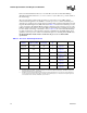
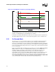
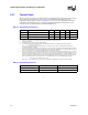
Table Of Contents
- Contents
- Revision History
- 1 Introduction
- 2 Electrical Specifications
- 2.1 FSB and GTLREF
- 2.2 Power and Ground Lands
- 2.3 Decoupling Guidelines
- 2.4 Voltage Identification
- 2.5 Reserved, Unused, and TESTHI Signals
- 2.6 FSB Signal Groups
- 2.7 GTL+ Asynchronous Signals
- 2.8 Test Access Port (TAP) Connection
- 2.9 FSB Frequency Select Signals (BSEL[2:0])
- 2.10 Absolute Maximum and Minimum Ratings
- 2.11 Processor DC Specifications
- 2.12 VCC Overshoot Specification
- 2.13 GTL+ FSB Specifications
- 3 Package Mechanical Specifications
- 4 Land Listing and Signal Descriptions
- 5 Thermal Specifications and Design Considerations
- 6 Features
- 7 Boxed Processor Specifications
- 8 Debug Tools Specifications

78 Datasheet
Thermal Specifications and Design Considerations
5.2.7 Thermal Diode
The processor incorporates an on-die thermal diode. A thermal sensor located on the system board
may monitor the die temperature of the processor for thermal management/long term die
temperature change purposes. Table 5-3 and Table 5-4 provide the diode parameter and interface
specifications. This thermal diode is separate from the Thermal Monitor’s thermal sensor and
cannot be used to predict the behavior of the Thermal Monitor.
§
Table 5-3. Thermal Diode Parameters
Symbol Parameter Min Typ Max Unit Notes
I
FW
Forward Bias Current 11 — 187 µA
1
NOTES:
1. Intel does not support or recommend operation of the thermal diode under reverse bias.
n Diode Ideality Factor 1.0083 1.011 1.023 —
2, 3, 4, 5
2. Characterized at 75 °C.
3. Not 100% tested. Specified by design characterization.
4. The ideality factor, n, represents the deviation from ideal diode behavior as exemplified by the diode equation:
I
FW
= I
S
* (e
qV
D
/nkT
–1)
where I
S
= saturation current, q = electronic charge, V
D
= voltage across the diode, k = Boltzmann Constant, and
T = absolute temperature (Kelvin).
5. Devices found to have an ideality factor in the range of +3 n to +5 n will create a temperature error approximately 2° C higher
than the actual temperature. To minimize any potential acoustic impact of this temperature error, T
CONTROL
will be increased
by 2° C on these parts. Processors with an ideality between ±3 n will not be affected.
R
T
Series Resistance 3.242 3.33 3.594 Ω
2, 3, 6
6. The series resistance, R
T
, is provided to allow for a more accurate measurement of the diode temperature. R
T
, as defined,
includes the lands of the processor but does not include any socket resistance or board trace resistance between the socket
and the external remote diode thermal sensor. R
T
can be used by remote diode thermal sensors with automatic series re-
sistance cancellation to calibrate out this error term. Another application is that a temperature offset can be manually calcu-
lated and programmed into an offset register in the remote diode thermal sensors as exemplified by the equation:
T
error
= [R
T
* (N-1) * I
FWmin
] / [nk/q * ln N]
where T
error
= sensor temperature error, N = sensor current ratio, k = Boltzmann Constant, q = electronic charge.
Table 5-4. Thermal Diode Interface
Signal Name Land Number Signal Description
THERMDA AL1 diode anode
THERMDC AK1 diode cathode