
Intel Celeron D Processor 300 Sequence

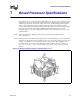
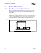
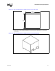
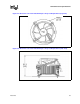
Table Of Contents
- Contents
- Revision History
- 1 Introduction
- 2 Electrical Specifications
- 2.1 FSB and GTLREF
- 2.2 Power and Ground Lands
- 2.3 Decoupling Guidelines
- 2.4 Voltage Identification
- 2.5 Reserved, Unused, and TESTHI Signals
- 2.6 FSB Signal Groups
- 2.7 GTL+ Asynchronous Signals
- 2.8 Test Access Port (TAP) Connection
- 2.9 FSB Frequency Select Signals (BSEL[2:0])
- 2.10 Absolute Maximum and Minimum Ratings
- 2.11 Processor DC Specifications
- 2.12 VCC Overshoot Specification
- 2.13 GTL+ FSB Specifications
- 3 Package Mechanical Specifications
- 4 Land Listing and Signal Descriptions
- 5 Thermal Specifications and Design Considerations
- 6 Features
- 7 Boxed Processor Specifications
- 8 Debug Tools Specifications
Datasheet 83
Boxed Processor Specifications
7 Boxed Processor Specifications
The Celeron D processor in the 775-land package will also be offered as an boxed Intel processor.
Boxed Intel processors are intended for system integrators who build systems from baseboards and
standard components. The boxed Celeron D processor in the 775-land package will be supplied
with a cooling solution. This chapter documents baseboard and system requirements for the
cooling solution that will be supplied with the boxed Celeron D processor in the 775-land package.
This chapter is particularly important for OEMs that manufacture baseboards for system
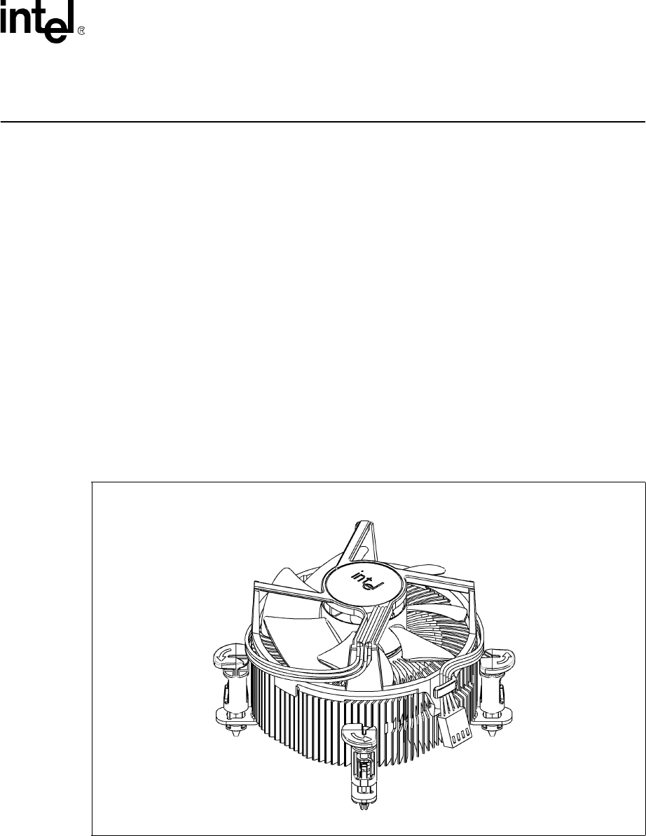
integrators. Figure 7-1 shows a mechanical representation of a boxed Celeron D processor in the
775-land package.
Note: Unless otherwise noted, all figures in this chapter are dimensioned in millimeters and
inches [in brackets].
Note: Drawings in this section reflect only the specifications on the boxed Intel processor product. These
dimensions should not be used as a generic keep-out zone for all cooling solutions. It is the system
designer’s responsibility to consider their proprietary cooling solution when designing to the
required keep-out zone on their system platforms and chassis. Refer to the Intel
®
Pentium
®
4
Processor on 90 nm Process in the 775-Land LGA Package Thermal Design Guide for further
guidance.
NOTE: The airflow of the fan heatsink is into the center and out of the sides of the fan heatsink.
Figure 7-1. Mechanical Representation of the Boxed Processor