
Intel Celeron D Processor 300 Sequence

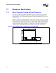
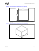
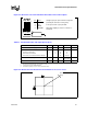
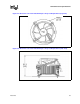
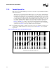
Table Of Contents
- Contents
- Revision History
- 1 Introduction
- 2 Electrical Specifications
- 2.1 FSB and GTLREF
- 2.2 Power and Ground Lands
- 2.3 Decoupling Guidelines
- 2.4 Voltage Identification
- 2.5 Reserved, Unused, and TESTHI Signals
- 2.6 FSB Signal Groups
- 2.7 GTL+ Asynchronous Signals
- 2.8 Test Access Port (TAP) Connection
- 2.9 FSB Frequency Select Signals (BSEL[2:0])
- 2.10 Absolute Maximum and Minimum Ratings
- 2.11 Processor DC Specifications
- 2.12 VCC Overshoot Specification
- 2.13 GTL+ FSB Specifications
- 3 Package Mechanical Specifications
- 4 Land Listing and Signal Descriptions
- 5 Thermal Specifications and Design Considerations
- 6 Features
- 7 Boxed Processor Specifications
- 8 Debug Tools Specifications
Datasheet 87
Boxed Processor Specifications
Figure 7-5. Boxed Processor Fan Heatsink Power Cable Connector Description
Pin
Signal
12
34
1
2
3
4
GND
+12 V
SENSE
CONTROL
Straight square pin, 4-pin terminal housing with
polarizing ribs and friction locking ramp.
0.100" pitch, 0.025" square pin width.
Match with straight pin, friction lock header on
mainboard.
Table 7-1. Fan Heatsink Power and Signal Specifications
Description Min Typ Max Unit Notes
+12V: 12 volt fan power supply 10.2 12 13.8 V
IC:
Peak Fan current draw
Fan start-up current draw
Fan start-up current draw maximum duration
—
—
1.1
—
1.5
2.2
1.0
A
A
Second
SENSE: SENSE frequency — 2 —
pulses per
fan revolution
1
NOTES:
1. Baseboard should pull this pin up to 5 V with a resistor.
CONTROL 2100 2500 2800 Hz
2,3
2. Open Drain Type, Pulse Width Modulated.
3. Fan will have a pull-up resistor to 4.75 V (maximum 5.25 V).
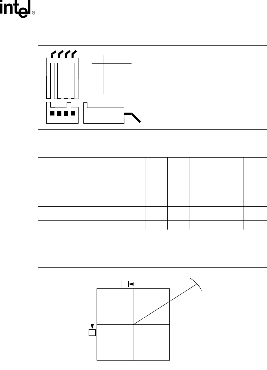
Figure 7-6. Baseboard Power Header Placement Relative to Processor Socket
B
C
R110
[4.33]