
Intel Celeron D Processor 300 Sequence

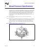
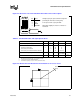
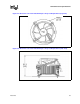
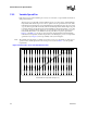
Table Of Contents
- Contents
- Revision History
- 1 Introduction
- 2 Electrical Specifications
- 2.1 FSB and GTLREF
- 2.2 Power and Ground Lands
- 2.3 Decoupling Guidelines
- 2.4 Voltage Identification
- 2.5 Reserved, Unused, and TESTHI Signals
- 2.6 FSB Signal Groups
- 2.7 GTL+ Asynchronous Signals
- 2.8 Test Access Port (TAP) Connection
- 2.9 FSB Frequency Select Signals (BSEL[2:0])
- 2.10 Absolute Maximum and Minimum Ratings
- 2.11 Processor DC Specifications
- 2.12 VCC Overshoot Specification
- 2.13 GTL+ FSB Specifications
- 3 Package Mechanical Specifications
- 4 Land Listing and Signal Descriptions
- 5 Thermal Specifications and Design Considerations
- 6 Features
- 7 Boxed Processor Specifications
- 8 Debug Tools Specifications

90 Datasheet
Boxed Processor Specifications
7.3.2 Variable Speed Fan
If the boxed processor fan heatsink 4-pin connector is connected to a 3-pin motherboard header, it
will operate as follows:
The boxed processor fan will operate at different speeds over a short range of internal chassis
temperatures. This allows the processor fan to operate at a lower speed and noise level, while
internal chassis temperatures are low. If internal chassis temperature increases beyond a lower
set point, the fan speed will rise linearly with the internal temperature until the higher set point
is reached. At that point, the fan speed is at its maximum. As fan speed increases, so does fan
noise levels. Systems should be designed to provide adequate air around the boxed processor
fan heatsink that remains cooler than the lower set point. These set points, represented in
Figure 7-9 and Table 7-2, can vary by a few degrees from fan heatsink to fan heatsink. The
internal chassis temperature should be kept below 38 ºC. Meeting the processor’s temperature
specification (see Chapter 5) is the responsibility of the system integrator.
Note: The motherboard must supply a constant +12 V to the processor’s power header to ensure proper
operation of the variable speed fan for the boxed processor (refer to Table 7-1) for the specific
requirements.
Figure 7-9. Boxed Processor Fan Heatsink Set Points
Lower Set Point
Lowest Noise Level
Internal Chassis Temperature (Degrees C)
X
YZ
Increasing Fan
Speed & Noise
Higher Set Point
Highest Noise Level