
Guide


I/O Subsystem
R
172 Intel
®
852GM Chipset Platform Design Guide
10.6.1.2. General Design Issues and Notes
Regardless of the architecture used, there are some general considerations.
1. The pull-up resistor size for the SMBus data and clock signals is dependent on the bus load (this
includes all device leakage currents). Generally the SMBus device that can sink the least amount
of current is the limiting agent on how small the resistor can be. The pull-up resistor cannot be
made so large that the bus time constant (Resistance X Capacitance) does not meet the SMBus
rise and fall time specification.
2. The maximum bus capacitance that a physical segment can reach is 400 pF.
3. The ICH4-M does not run SMBus cycles while in S3.
4. SMBus devices that can operate in S3 must be powered by the V
CC
_
SUSPEND
supply.
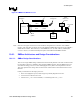
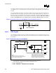
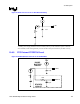
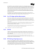
10.6.1.3. High Power and Low Power Mixed Architecture
This design allows for current isolation of high and low current devices while also allowing SMBus
devices to communicate during the S3 state. Keeping non-essential devices on the core supply
minimizes VCC_SUSPEND leakage. This is accomplished by the use of a “FET” to isolate the devices
powered by the core and suspend supplies. See Figure 87.
Figure 87. High Power/Low Power Mixed V
CC
_
SUSPEND
/V
CC
_
CORE
Architecture
ICH4
High
Current
Low
Current
VccSusVccSus3_3
Vcc
SMBus
Devices running in Standby
Non-Standby devices
Vcc
VccSus VccSus3_3
SMBus
Vcc
SMBus
Devices running in Standby
Non -Standby devices
Vcc
Current Isolation
Logic
Buffered Power Good Signal From
Power Supply
Buffered Power Good Signal From
Power Supply
1. The bus switch must be powered by V
CC
_
SUSPEND.
2. Devices that are powered by the V
CC
_
SUSPEND
well must not drive into other devices that are
powered off. This is accomplished with the “bus switch”.
3. The bus bridge can be a device like the Phillips* PCA9515.
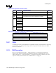
10.6.1.4. Calculating the Physical Segment Pull-Up Resistor
The following tables are provided as a reference for calculating the value of the pull-up resistor that may
be used for a physical bus segment. If any physical bus segment exceeds 400 pF, then a bus bridge
device like the Phillips* PCA9515 must be used to separate the physical segment into two segments that
individually have a bus capacitance less than 400 pF.