
Guide


I/O Subsystem
R
176 Intel
®
852GM Chipset Platform Design Guide
For further information on the RTC, please consult Application Note AP-728
ICH Family Real Time
Clock (RTC) Accuracy and Considerations Under Test Conditions
. This application note is valid for the
ICH4-M.
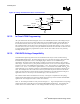
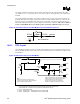
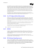
Even if the ICH4-M internal RTC is not used, it is still necessary to supply a clock input to RTCX1 of
the ICH4-M because other signals are gated off that clock in suspend modes. However, in this case, the
frequency accuracy (32.768 kHz) of the clock inputs is not critical; a single clock input can be driven
into RTCX1with RTCX2 left as no connect; Figure 91 illustrates the connection.
This is not a validated
feature on the ICH4-M. Please note that the peak-to-peak swing on RTCX1 cannot exceed 1.0 V.
Figure 91. External Circuitry for the ICH4-M Where the Internal RTC Is Not Used
Internal
External
RTCX1 RTCX2
5M
32 KHz
No Connection
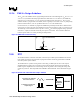
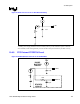
10.8.1. RTC Crystal
The ICH4-M RTC module requires an external crstal oscillating source of 32.768 kHz connected on the
RTCX1 and RTCX2 balls. Figure 92 documents the external circuitry that comprises the oscillator of the
ICH4-M RTC.
Figure 92. External Circuitry for the ICH4-M RTC
32.768 kHz
Xtal
0.047uF
10MΩ
VCCRTC
RTCX2
RTCX1
VBIAS
Vbatt
1uF
1kΩ
3.3V Sus
18pF
18pF
10MΩ
C1 C2
C3
R1
R2
Notes
Reference Designators Arbitrarily Assigned
3.3V Sus is Active Whenever System Plugged In
Vbatt is Voltage Provided By Battery
VBIAS, VCCRTC, RTCX1, and RTCX2 are ICH4 pins
VBIAS is used to bias the ICH4 Internal Oscillator
VCCRTC powers the RTC well of the ICH4
RTCX1 is the Input to the Internal Oscillator
RTCX2 is the feedback for the external crystal
NOTES:
1. The exact capacitor value needs to be based on what the crystal maker recommends.
(Typical values for C1 and C2 are 18 pF, based on crystal load of 12.5 pF).
2. V
CCRTC
: Power for RTC Well
3. RTCX2: Crystal Input 2 – Connected to the 32.7 68-kHz crystal.
4. RTCX1: Crystal Input 1 – Connected to the 32.7 68-kHz crystal.