
Guide


I/O Subsystem
R
Intel
®
852GM Chipset Platform Design Guide 183
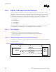
Table 76. LAN LOM Routing Summary
LAN Routing
Requirements
Maximum Trace Length Signal
Referencing
LAN Signal Length Matching
5 on 10 4.5 to 12 inches Ground Data signals must be equal to or no
more than 0.5 inches (500 mils)
shorter than the LAN clock trace.
10.9.1.2. Signal Routing and Layout
Platform LAN Connect Interface signals must be carefully routed on the motherboard to meet the timing
and signal quality requirements of this interface specification. The following are some general
guidelines that should be followed. Intel recommends that the board designer simulate the board routing
to verify that the specifications are met for flight times and skews due to trace mismatch and crosstalk.
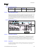
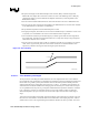
On the motherboard the length of each data trace is either equal in length to the LAN_CLK trace or up
to 0.5 inches shorter than the LAN_CLK trace. (LAN_CLK should always be the longest motherboard
trace in each group.)
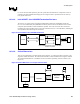
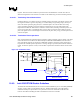
Figure 97. LAN_CLK Routing Example
LAN_CLK
LAN_RXD0
LAN_CLK
LAN_RXD0
LAN_CLK
LAN_RXD0
10.9.1.3. Crosstalk Consideration
Noise due to crosstalk must be carefully controlled to a minimum. Crosstalk is the key cause of timing
skews and is the largest part of the t
RMATCH
skew parameter. t
RMATCH
is the sum of the trace length
mismatch between LAN_CLK and the LAN data signals. To meet this requirement on the board, the
length of each data trace is either equal to or up to 0.5 inches shorter than the LAN_CLK trace.
Maintaining at least 100 mils of spacing should minimize noise due to crosstalk from non-PLC signals.
10.9.1.4. Impedances
The motherboard impedances should be controlled to minimize the impact of any mismatch between the
motherboard. An impedance of 55
Ω ± 15% is strongly recommended; otherwise, signal integrity
requirements may be violated.