
Guide


I/O Subsystem
R
Intel
®
852GM Chipset Platform Design Guide 185
For a noise free and stable operation, place the crystal and associated discrete components as close as
possible to the Intel 82562ET/EM, keeping the trace length as short as possible and do not route any
noisy signals in this area.
10.9.2.3. Intel 82562ET / Intel 82562EM Termination Resistors
The 100 Ω ± 1% resistor used to terminate the differential transmit pairs (TDP/TDN) and the 121
Ω ± 1% receive differential pairs (RDP/RDN) should be placed as close to the Platform LAN connect
component (Intel 82562ET or Intel 82562EM) as possible. This is due to the fact these resistors are
terminating the entire impedance that is seen at the termination source (i.e. Intel 82562ET), including the
wire impedance reflected through the transformer.
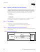
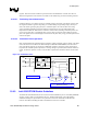
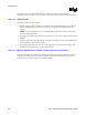
Figure 98. Intel 82562ET / Intel 82562EM Termination
82562ET
Magnetics
Module
RJ45LAN Connect Interface
ICH4-M
Place termination resistors as close to the Intel®
82562ET as possible
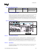
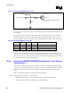
10.9.2.4. Critical Dimensions
There are two dimensions to consider during layout. Distance ‘A’ from the line RJ-45 connector to the
magnetics module and distance ‘B’ from the Intel 82562ET or Intel 82562EM to the magnetics module.
The combined total distances A and B must not exceed 4 inches (preferably, less than 2 inches). (See
Figure 99.)
Figure 99. Critical Dimensions for Component Placement
82562ET
B
A
EEPROM
Magnetics
Module
Line
RJ45
ICH4-M