
Guide


I/O Subsystem
R
190 Intel
®
852GM Chipset Platform Design Guide
decoupling capacitors should be sufficiently large in diameter to decrease series inductance.
Additionally, the PLC should not be closer than one inch to the connector/magnetics/edge of the board.
10.9.4.1.2. Signal Isolation
Some rules to follow for signal isolation:
• Separate and group signals by function on separate layers if possible. Maintain a gap of 100 mils
between all differential pairs (Ethernet) and other nets, but group associated differential pairs
together.
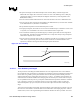
NOTE: Over the length of the trace run, each differential pair should be at least 0.3 inches away
from any parallel signal traces.
• Physically group together all components associated with one clock trace to reduce trace length and
radiation.
• Isolate I/O signals from high speed signals to minimize crosstalk, which can increase EMI emission
and susceptibility to EMI from other signals.
• Avoid routing high-speed LAN traces near other high-frequency signals associated with a video
controller, cache controller, CPU, or other similar devices.
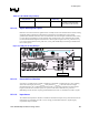
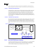
10.9.4.1.3. Magnetics Module General Power and Ground Plane Considerations
To properly implement the common mode choke functionality of the magnetics module the chassis or
output ground (secondary side of transformer) should be separated from the digital or input ground
(primary side) by a physical separation of 100-mils minimum.