
Guide

Mobile Intel Pentium 4 Processor–M and Mobile Intel Celeron Processor FSB Design Guidelines
R
Intel
®
852GM Chipset Platform Design Guide 33
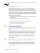
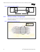
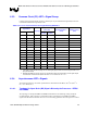
4.1.1. Return Path Evaluation
The return path is the route current takes to return to its source. It may take a path through ground
planes, power planes, other signals, integrated circuits, vias, VRMs, etc. Think of the return path as
following a path of least impedance back to the original source. Discontinuities in the return path often
have signal integrity and timing effects that are similar to the discontinuities in the signal conductor.
Therefore, the return paths need to be given similar considerations. A simple way to evaluate return path
parasitic inductance is to draw a loop that traces the current from the driver through the signal conductor
to the receiver, and then back through the ground/power plane to the driver again. The smaller the area
of the loop, the lower the parasitic inductance will be.
The following set of return path rules apply:
• Always trace out the return current path and provide as much care to the return path as the path of
the signal conductor.
• Decoupling capacitors do not adequately compensate for a plane split.
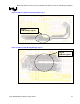
• Do not allow splits in the reference planes in the path of the return current.
• Do not allow routing of signals on the reference planes near Front Side Bus signals.
• Maintain Vss as a reference plane for all Front Side Bus signals.
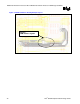
• Do not route over via anti-pads or socket anti-pads.
4.2. Processor Configuration
This section provides more details for routing Mobile Intel Pentium 4 Processor–M- based systems. This
information is preliminary and subject to change. Both recommendations and considerations are
presented.
For proper operation of the Mobile Pentium 4 Processor-M and the Intel 852GM chipset, it is necessary
that the system designer meet the timing and voltage specifications of each component. The following
recommendations are Intel’s best guidelines based on extensive simulation and experimentation that
make assumptions, which may be different than an OEM's system design. The most accurate way to
understand the signal integrity and timing of the Front Side Bus in your platform is by performing a
comprehensive simulation analysis. It is conceivable that adjustments to trace impedance, line length,
termination impedance, board stackup and other parameters can improve system performance.
Refer to the Mobile Intel
®
Pentium
®
4 Processor–M Datasheet for a Front Side Bus signal list, signal
types and definitions.
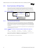
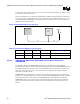
4.3. General Topology and Layout Design Guidelines
The following topology and layout guidelines are based on routing recommendations implemented on
Intel Customer reference board. The guidelines are derived from empirical testing with Intel 852GM
chipset package models. Below are the design recommendations for the data, address, strobes, and
common clock signals. For the following discussion, the pad is defined as the attach point of the silicon
die to the package substrate.