
Guide

Mobile Intel Pentium 4 Processor–M and Mobile Intel Celeron Processor FSB Design Guidelines
R
Intel
®
852GM Chipset Platform Design Guide 35
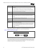
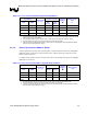
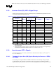
Table 2. Processor Front Side Bus Data Signal Routing Guidelines
Signal Names Total Trace Length
CPU GMCH
Transmission
Line Type
Min
(inches)
Max
(inches)
Nominal
Impedance
(Ω)
Width & Spacing
(mils)
1:3
DBI[3:0]# DINV[3:0]# Strip-line 0.5 5.5 55 ± 15% 4 & 12
D[63:0]# HD[63:0]# Strip-line 0.5 5.5 55 ±15% 4 & 12
DSTBN[3:0]# HDSTBN[3:0]# Strip-line 0.5 5.5 55 ± 15% 4 & 12
DSTBP[3:0]# HDSTBP[3:0]# Strip-line 0.5 5.5 55 ±15% 4 & 12
NOTES:
1. The Data signals within each group must be routed to within ± 0.100 inches of its associated “reference” strobe
(within the min & max of both strobe).
2. The complement strobe must be routed to within ± 0.025 inches of the associate “reference” strobe.
3. All traces within each signal group must be routed on the same layer (required).
4. Intel recommends that length of the strobes be centered to the average length of associated data or address
traces to maximize setup/hold time margins.
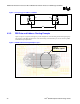
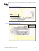
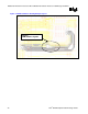
4.3.1.2. Source Synchronous Address Group
Address signals follow the same rules as data signals except they should be routed to the same pad-to-
pad length within ± 0.200 inches of the associated strobes. Address signals may change layers if the
reference plane remains Vss.
An address strobe should be routed to a length equal to their corresponding signal group's mean pad-to-
pad length ± 0.025 inches.
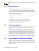
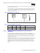
Table 3. Processor Front Side Bus Address Signal Routing Guidelines
Signal Names Total Trace Length
CPU GMCH
Transmission
Line Type
Min
(inches)
Max
(inches)
Nominal
Impedance
(Ω)
Width & Spacing
(mils)
A[31:3]# HA[31:3]# Strip-line 0.5 6.5 55 ± 15% 4 & 8
REQ[4:0]# HREQ[4:0]# Strip-line 0.5 6.5 55 ± 15% 4 & 8
ADSTB[1:0]# HADSTB[1:0]# Strip-line 0.5 6.5 55 ± 15% 4 & 8
NOTES:
1. The Address signals within each group must be routed to within ± 0.200 of its associated strobe.
2. All traces within each signal group must be routed on the same layer (required).
3. It is recommended that length of the strobes be centered to the average length of associated data or address
traces to maximize setup/hold time margins.