
Datasheet

7
Package Mechanical Specifications and Pin Information
2 Package Mechanical
Specifications and Pin
Information
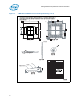
2.1 Package Mechanical Specifications
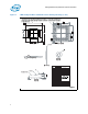
The Celeron processor 550 series will have two variants, both may be available in a
478-pin Micro-FCPGA (not shown in this addendum, see Intel Celeron Processor 500
Series Datasheet for reference) or 479-pin Micro-FCBGA package (illustrated in this
addendum). Package mechanical dimensions are shown in Figure 1 for the 1 MB
configured variant and Figure 3 for the 1 MB variant.
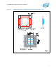
2.1.1 Processor Component Keep-Out Zones
The processor may contain components on the substrate that define component keep-
out zone requirements. A thermal and mechanical solution design must not intrude into
the required keep-out zones. Decoupling capacitors are typically mounted in the keep-
out areas. The location and quantity of the capacitors may change but will remain
within the component keep-in. See Figure 2 and Figure 4 for keep-out zones.
2.1.2 Package Loading Specifications
Maximum mechanical package loading specifications are given in Figure 1 and Figure 3
for the 1 MB configured variant and 1 MB variant respectively. These specifications are
static compressive loading in the direction normal to the processor. This maximum load
limit should not be exceeded during shipping conditions, standard use condition, or by
the thermal solution. In addition, there are additional load limitations against transient
bend, shock, and tensile loading. These limitations are more platform specific and
should be obtained by contacting your field support. Moreover, the processor package
substrate should not be used as a mechanical reference or load-bearing surface for the
thermal or mechanical solution.
2.1.3 Processor Mass Specifications
The typical mass of the 1 MB configured variant and 1 MB variant is shown in Figure 1
and Figure 3. This mass includes all the components that are included in the package.