
Design Guide
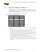


System Memory Design Guidelines (DDR-SDRAM) for SO-DIMM configuration
R
118 Intel
®
855GM/855GME Chipset Platform Design Guide
allows for the best correlation of thermal sensor temperature to chassis or notebook surface temperature.
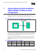
See Figure 52 for details.
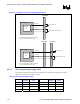
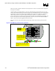
Assuming airflow is negligible within a system, the optimal placement of the thermal sensor is on the
surface of the motherboard directly beneath the shadow of an SO-DIMM module centered longitudinally
and laterally in relation to the outline of the SO-DIMM. The thermal sensor should have a form factor
small enough to allow it to fit beneath double-sided memory modules (i.e. modules with memory
devices on both sides of a module). If placement within the outline of an SO-DIMM is not possible, then
the next best option is to locate it within approximately 15 mm (0.6 inches) of the outline/SO-DIMM
shadow. Again, this assumes negligible effects from airflow.
Please refer to the Intel (R) 855GM (Montara-MG) Chipset Mobile Thermal Design Guide for more
details.
Figure 52. DDR Memory Thermal Sensor Placement
Top View – SO-DIMM
Side View – SO-DIMM
SO - DIMM outline will be not be as
Best Location
is sensor
15mm
15mm
Top View – SO-DIMM
Sensor location within approx 15mm of
SO-DIMM outline will not be as effective
at controlling fast transient temperature
changes.
Best Location is sensor
under SO-DIMM. May not
be mechanically feasible
in all designs due to small
gap between SO-DIMM
and motherboard.
15mm
15mm
Hashed Area:
Recommended area for
DRAM ETS# sensor on
motherboard.