
Design Guide


System Memory Design Guidelines (DDR-SDRAM) for Memory Down Configuration
R
120 Intel
®
855GM/855GME Chipset Platform Design Guide
7. System Memory Design Guidelines
(DDR-SDRAM) for Memory Down
Configuration
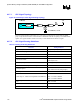
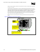
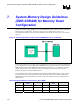
This section contains routing guidelines for a Micro-DIMM and memory soldered onto the motherboard
(Memory Down) configuration. The order of routing for this configuration is specific. It is
recommended the designer route to the Micro-DIMM first and the Memory Down devices second (See
Figure 53.)
Figure 53. Recommended Device Order for Micro-DIMM/Memory Down Combination
Trace length parameters for the memory down configuration are based on trace length recommendations
given in the PC2700 Unbuffered DDR Micro-DIMM Reference Design Specification, PC2700/PC2100
DDR SDRAM Unbuffered SO-DIMM Reference Design Specification rev 1.1, simulation and routing
studies. The parameters were simulated at various trace lengths to provide designers with greater
flexibility in placing and routing SDRAM devices.
These guidelines support PC2100 (266MHz) and PC2700 (333MHz) SDRAM devices. Table 1 shows
the supported memory configurations for the Micro-DIMM per the PC2700 Unbuffered DDR Micro-
DIMM Reference Design Specification and Table 39 shows the supported memory configurations for
Memory Down.
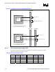
Table 39. Supported Memory Configurations - Micro-DIMM
Device Type Module Bus
Width
Device Width #Devices Physical
Banks
Capacity
TSOP x64 x16 4 1 32-256 MB
BGA x64 x16 4 1 32-512 MB
BGA x64 x16 8 2 64 MB – 1 GB