
Design Guide

System Memory Design Guidelines (DDR-SDRAM) for Memory Down Configuration
R
Intel
®
855GM/855GME Chipset Platform Design Guide 121
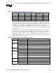
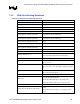
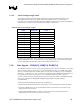
Table 40. Supported Memory Configurations - Memory Down
Device Type Bus Width Device Width #Devices Physical
Banks
Max Capacity
TSOP x64 x16 4 1 256 MB
BGA x64 x16 4 1 256 MB
BGA x64 x16 8 2 512 MB
BGA x64 x8 8 1 512 MB
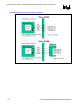
These guidelines support standard TSOP and BGA packages in 64Mb, 128Mb, 256Mb, and 512Mb
memory densities. Stacked memory technologies are not supported (i.e. Stacked TSOP, DDP). The
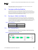
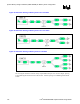
following SDRAM device placement strategies are recommended for the different device types and
configurations. For a 4-TSOP device configuration, two on the top and two on the bottom is
recommended. For a 4-BGA device configuration, all devices are on the same side of the motherboard.
For an 8-BGA device configuration, four devices are placed on one side of the motherboard and four on
the opposite side.
The 855GM/GME chipset Double Data Rate (DDR) SDRAM system memory interface consists of
SSTL-2 compatible signals. These SSTL-2 compatible signals have been divided into several signal
groups: Data, Control, Command, CPC, Clock, and Feedback signals. Table 41 summarizes the
different signal grouping. Refer to the Intel
®
855GM/GME Chipset External Design Specification for
details on the signals listed. ECC is not supported by these routing guidelines. Data bits SDQ[71:64],
SDQS[8], and SDM[8] are no connects.
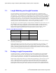
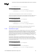
Table 41. Montara-GM GMCH Chipset DDR Signal Groups
Group Signal Name Description
SCK[4,3,1,0] DDR-SDRAM Differential Clocks
Clocks
SCK#[4,3,1,0] DDR-SDRAM Inverted Differential Clocks
SDQ[63:0] Data Bus
SDQS[8:0] Data Strobes
Data
SDM[8:0] Data Mask
SCKE[3:0] Clock Enable - (One per Device Row)
Control
SCS#[3:0] Chip Select - (One per Device Row)
SMA[12:6,3,0] Memory Address Bus
SBA[1:0] Bank Select
SRAS# Row Address Select
SCAS# Column Address Select
Command
SWE# Write Enable
SMA[5,4,2,1] Command per Clock (Micro-DIMM)
CPC
SMAB[5,4,2,1] Command per Clock (Memory Down)
RCVENOUT# Receive Enable Output (no external connection)
Feedback
RCVENIN# Receive Enable Input (no external connection)