
Design Guide


System Memory Design Guidelines (DDR-SDRAM) for Memory Down Configuration
R
Intel
®
855GM/855GME Chipset Platform Design Guide 141
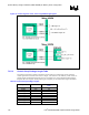
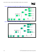
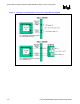
Figure 65. Control Signal Routing GMCH to Memory Down 1x16/2x16 4 Load BGA
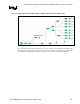
Figure 66. Control Signal Routing GMCH to Memory Down 1x8 8 Loads BGA
The control signals should be routed using 2 to 1 trace spacing to trace width ratio for signals within the
DDR group, except clocks and strobes. There should be a minimum of 20-mils of spacing to non-DDR
related signals. Control signals should be routed on inner layers with minimized external trace lengths.