
Design Guide

Integrated Graphics Display Port
R
160 Intel
®
855GM/855GME Chipset Platform Design Guide
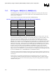
Equation 1.
)2.73(*32
)4/(
uA
Vbg
Ireference
Vreference
REFSET ==
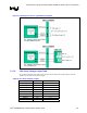
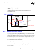
A 127 Ω 1% precision resistor value is the recommend value to use. See Figure 77 for the
recommended Rset placement.
Note: When using 855GME platform with external graphics only, Rset resistor is not needed.
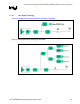
Figure 77. Refset Placement
Large via or multiple
vias straight down to
ground plane
IREF ball
Refset
Resistor
Resistor
Solder
Pads
Top Side of
Motherboard
Short, wide route
connecting the
resistor to the IREF
ball
No toggling signals
should be routed near this
reference resistor
127Ω, 1%, 1/16W
SMT metal film
resistor
Intel 855GM
Chipset
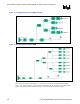
8.1.3. RAMDAC Board Design Guidelines
Care should be taken when routing the analog RAMDAC signals. This is especially true to successfully
support high display resolution where pixel frequency can be as high as 350 MHz. Intel recommends
that each analog R, G, B signal be routed single-endedly. The analog RGB signals should be routed with
an impedance of 37.5 Ω. Intel recommends that these routes be routed on an inner routing layer and that
it be shielded with VSS planes, if possible. Spacing between DAC channels and to other signals should
be maximized; 20-mil spacing is recommended. The RGB signals require pi filters that should be placed
near the VGA connector. It consists of two 3.3-pF caps with a 75 Ω ferrite bead at 100-MHz between
them. The RGB signals should have a 75-Ω, 1% terminating pull-down resistor. The complement signals
(R#, G#, and B#) should be grounded to the ground plane.
Note: When using 855GME platform with external graphics only, the RGB 75-Ω termination resistors are not
needed.
Intel recommends that the pi filter and terminating resistors be placed as close as possible to the VGA
connector. After the 75-Ω termination resistor, the RGB signals routing to the pi-filters and the VGA
connector should ideally be routed with 75-Ω impedance (~ 5 mil traces), or as close to 75-Ω
impedance as possible.