
Design Guide

Integrated Graphics Display Port
R
Intel
®
855GM/855GME Chipset Platform Design Guide 161
The RGB signals also require protection diodes between 1.5 V and ground. These diodes should have
low C ratings (~5 pF max) and small leakage current (~ 10 µA at 120˚C) and should be properly
decoupled with a 0.1-µF cap. These diodes and decoupling should be placed to minimize power rail
inductance. The choice between diodes (or diode packs) should comprehend the recommended electrical
characteristics in addition to cost.
The RGB signals should be length matched as closely as possible (from the GMCH to the VGA
connector) and should not exceed 200 mils of mismatch.
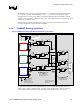
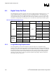
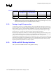
8.1.4. RAMDAC Routing Guidelines
Figure 78. GMCH DAC Routing Guidelines with Docking Connector
Do NOT route any high-
frequency signals in the
shaded area
RED
Red
DAC
Channel
RED#
Motherboard
GREEN
Green
DAC
Channel
GREEN#
BLUE
Blue
DAC
Channel
BLUE#
VGA
Connector
on main
board
Pin 1 -
Red
Pin 2 -
Green
Pin 3 -
Blue
Place components in
Close proximity to VGA
& Docking connectors
Place ESD diodes to
minimize power rail
inductance – place C1 as
close to diodes as possible
REFSET
IREF VSSDACA
VCCDACA1 VCCDACA2
1.5V
C1 C2
Place C1 and C2 as
close to package as
possible
FB
C
C
1.5V
D
D
C1
37.5
Ω
traces
R1
FB
C
C
1.5V
D
D
C1
37.5
Ω
traces
R1
FB
C
C
1.5V
D
D
C1
37.5
Ω
traces
75
Ω
trace
R1
Switch
Switch
75
Ω
trace
Switch
Docking
Connector
75
Ω
trace
R1
FB
C
C
VGA
Connector
on docking
station
Red
Green
Blue
R1
FB
C
C
R1
FB
C
C
Place components in
Close proximity to VGA
& Docking connectors
Docking Station
75
Ω
trace
75
Ω
trace
75
Ω
trace
37.5
Ω
trace
37.5
Ω
trace
37.5
Ω
trace
The DAC channel (red, green, blue) outputs should be routed as single-ended shielded routes to an
analog switch to support a docking station. An analog switch should be used in order to provide the
proper termination that is required for high-performance video signal integrity. See Figure 79.