
Design Guide

Integrated Graphics Display Port
R
166 Intel
®
855GM/855GME Chipset Platform Design Guide
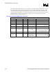
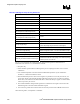
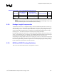
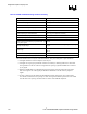
Table 59. LVDS Signal Group Routing Guidelines
Parameter Definition
Signal Group LVDS
Topology Differential Pair Point to Point
Reference Plane Ground Referenced
Differential Mode Impedance (Zdiff) 100 Ω ± 15%
Nominal Trace Width 4 mils
Nominal Pair Spacing (edge to edge) 7 mils
Minimum Pair to Pair Spacing
(see exceptions for breakout region below)
20 mils
Minimum Serpentine Spacing 20 mils
Minimum Spacing to Other LVDS Signals
(see exceptions for breakout region below)
20 mils
Minimum Isolation Spacing to non-LVDS Signals 20 mils
Maximum Via Count 2 (per line)
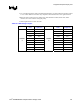
Package Length Range
550 mils ± 150mils
(See LVDS package length Table 60 for exact lengths)
Total Length Max 10”
Data to Clock Length Matching Match all segments to within +/- 20 mils of associated clock pair
Clock to Clock# Length Matching (Total Length) Match clocks to +/- 20 mils
Data to Data# Length Matching (Total Length) Match data to +/- 20 mils
Breakout Exceptions
(Reduced geometries for GMCH breakout region)
Breakout section should be as shorter as possible. Try to
maintain trace width as 4 mils, spacing 7 mils, while the spacing
between pairs can be 10-20 mils.
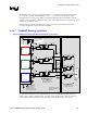
The traces associated with the LVDS Transmitter timing domain signals are differential traces
terminated across 100 Ω ± 15 % and should be routed as:
• Strip-line only.
• Isolate all other signals from the LVDS signals to prevent coupling from other sources onto the
LVDS lines.
• Use controlled impedance traces that match the differential impedance of your transmission
medium (i.e. cable) and termination resistor
• Run the differential pair trace lines as close together as possible as soon as they leave the IC, not
greater than 10 mils. This will help eliminate reflections and ensure noise is coupled as common
mode. Plus, noise induced on the differential lines is much more likely to appear as common mode,
which is rejected by the receiver.
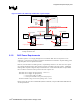
• The LVDS Transmitter timing domain signals have a maximum trace length of 10.0 inches. This
maximum applies to all of the LVDS Transmitter signals.
• Traces must be ground referenced and must not switch layers between the GMCH and connector.
When choosing cables, it is important to remember: