
Design Guide

Integrated Graphics Display Port
R
168 Intel
®
855GM/855GME Chipset Platform Design Guide
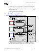
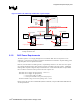
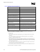
8.3. Digital Video Out Port
The GMCH DVO port interface supports a wide variety of third party DVO compliant devices (e.g. TV
encoder, TMDS transmitter or integrated TV encoder and TMDS transmitter). The GMCH has two
dedicated Digital Video Out Ports, DVOB and DVOC. Intel’s DVO port is a 1.5-V only interface that
can support transactions up to 165 MHz. Some of the DVO port command signals may require voltage
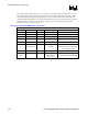
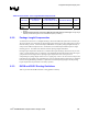
translation circuit depending on the third party device. The table below lists the DVO interface signals.
Table 61. DVO Interface Signal Groups
Signal Group
GMCH Signal
Name
Signal Type Signal Group
GMCH Signal
Name
Signal Type
DVOBFLDSTL Input DVOCFLDSTL Input
DVOBHSYNC Output DVOCHSYNC Output
DVOBVSYNC Output DVOCVSYNC Output
DVOBBLANK# Output DVOCBLANK# Output
DVOBD[11:0] Output DVOCD[11:0] Output
DVOBCLK
(DVOBCLK[0])
Output Strobe
DVOCCLK
(DVOCCLK[0])
Output Strobe
DVOB
DVOBCLK#
(DVOBCLK[1])
Output Strobe
DVOC
DVOCCLK#
(DVOCCLK[1])
Output Strobe
DVOBCCLKINT Input DVORCOMP
DVOBCINTR#
Input
Voltage
Reference,
RCOMP GVREF
ADDID[7:0] Input
Common
Signals for
Both DVO
Ports
DVODETECT Input
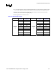
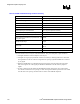
8.3.1. Length Matching Requirements
The routing guidelines presented in the following subsections define the recommended routing
topologies, trace width and spacing geometries, and absolute minimum and maximum routed lengths for
each signal group, which are recommended to achieve optimal SI and timing. In addition to the absolute
length limits provided in the individual guideline tables, more restrictive length matching requirements
are also provided which further restrict the minimum to maximum length range of each signal group
with respect to clock strobe, as required to guarantee adequate timing margins. Refer to Table 62 for
DVO length matching requirements.