
Design Guide

Integrated Graphics Display Port
R
174 Intel
®
855GM/855GME Chipset Platform Design Guide
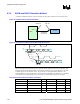
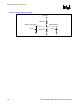
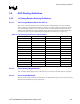
Figure 83. Generic Module Connector Parasitic Model
Motherboard Module
2.21 pF
C
2
2.21 pF
C
1
2.5nH
RL
20mΩ
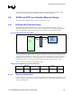
8.5. DVO GMBUS and DDC Interface Considerations
The GMCH DVOB and/or DVOC port controls the video front-end devices via the GMBUS (I2C)
interface. DDCADATA and DDCACLK should be connected to the CRT connector. The GMBUS
should be connected to the DVO device, as required by the specifications for those devices. The
protocol and bus may be used to configure registers in the TV encoder, TMDS transmitter, or any other
external DVI device. The GMCH also has an option to utilize the DDCPCLK and DDCPDATA to
collect EDID (Extended Display Identification) from a digital display panel.
Pull-ups (or pull-ups with the appropriate value derived from simulating the signal) typically ranging
from 2.2 kΩ to 10 kΩ are required on each of these signals.
The following GMCH signal groups list the six possible GMBUS pairs.
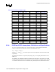
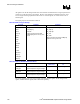
Table 67. GMBUS Pair Mapping and Options
Pair
#
Signal Name Buffer
Type
Description Notes
DDCADATA 0
DDCACLK
3.3 V DDC for Analog monitor (CRT)
connection.
This cannot be shared with other
DDC or I2C pairs due to legacy
monitor issues.
LCLKCTRLA
1
LCLKCTRLB
3.3 V For control of SSC clock generator
devices down on motherboard.
If SSC is not supported then can
be used for DVOB or DVOC
GMBUS.
DDCPDATA
2
DDCPCLK
3.3 V DDC for Digital Display connection via
the integrated LVDS display port for
support for EDID panel.
If EDID panels are not
supported. Can optionally use as
GMBUS for DVOB or DVOC.
MDVIDATA
3
MDVICLK
1.5 V GMBUS control of DVI devices (TMDS
or TV encoder)
Can optionally use as GMBUS
for DVOB or DVOC.
MI2CDATA
4
MI2CCLK
1.5 V GMBUS control of DVI devices (TMDS
or TV encoder)
Can optionally use as GMBUS
for DVOB or DVOC.
MDDCDATA
5
MDDCCLK
1.5 V DDC for Digital Display connection via
TMDS device
Can optionally use as GMBUS
for DVOB or DVOC.
NOTE: All GMBUS pairs can be optionally programmed to support any interface and is programmed through the
BMP utility.
If any of GMBUS pairs are not used, 2.2 k – 100 kΩ pull-up (or pull-ups with the appropriate value
derived from simulating the signal) resistors are required, except for CRT DDCADATA/DDCCLK and